62 - Box Joint Jig, страница 28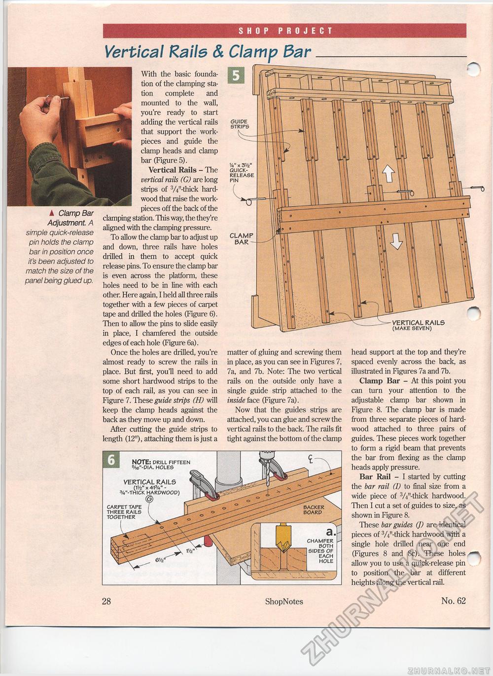
SHOP PROJECT Vertical Raile & A Clamp Bar Adjustment. A simple quick-release pin holds the clamp bar in position once it's been adjusted to match the size of the panel being glued up. With the basic foundation of the clamping station complete and mounted to the wall, you're ready to start adding the vertical rails that support the work-pieces and guide the clamp heads and clamp bar (Figure 5). Vertical Rails - The vertical rails (G) are long strips of 3/i"-thick hardwood that raise the work-pieces off the back of the clamping station. This way, the they're aligned with the clamping pressure. To allow the clamp bar to adjust up and down, three rails have holes drilled in them to accept quick release pins. To ensure the clamp bar is even across the platform, these holes need to be in line with each other. Here again, I held all three rails together with a few pieces of carpet tape and drilled the holes (Figure 6). Then to allow the pins to slide easily in place, I chamfered the outside edges of each hole (Figure 6a). Once the holes are drilled, you're almost ready to screw the rails in place. But first, you'll need to add some short hardwood strips to the top of each rail, as you can see in Figure 7. These guide strips (H) will keep the clamp heads against the back as they move up and down. After cutting the guide strips to length (12"), attaching them is just a VERTICAL RAILS (1'/2" x 41%" -3/4"-THICK CARPET TAPE THREE RAILS TOGETHER Clamp 3arNOTE: DRILL FIFTEEN 5/i6"-DIA. HOLES GUIDE STRIPS CLAMP BAR 'A" x 3V2" QUICK-RELEASE PIN matter of gluing and screwing them in place, as you can see in Figures 7, 7a, and 7b. Note: The two vertical rails on the outside only have a single guide strip attached to the inside face (Figure 7a). Now that the guides strips are attached, you can glue and screw the vertical rails to the back. The rails fit tight against the bottom of the clamp VERTICAL RAILS (MAKE SEVEN) head support at the top and they're spaced evenly across the back, as illustrated in Figures 7a and 7b. Clamp Bar - At this point you can turn your attention to the adjustable clamp bar shown in Figure 8. The clamp bar is made from three separate pieces of hardwood attached to three pairs of guides. These pieces work together to form a rigid beam that prevents the bar from flexing as the clamp heads apply pressure. Bar Rail - I started by cutting the bar rail (I) to final size from a wide piece of 3/i"-thick hardwood. Then I cut a set of guides to size, as shown in Figure 8. These bar guides (J) are identical pieces of 3/i"-tiiick hardwood with a single hole drilled near one end (Figures 8 and 8c). These holes allow you to use a quick-release pin to position the bar at different heights along the vertical rail. BOARD CHAMFER BOTH SIDES OF EACH HOLE 28 ShopNotes No. 62 |


