62 - Box Joint Jig, страница 29
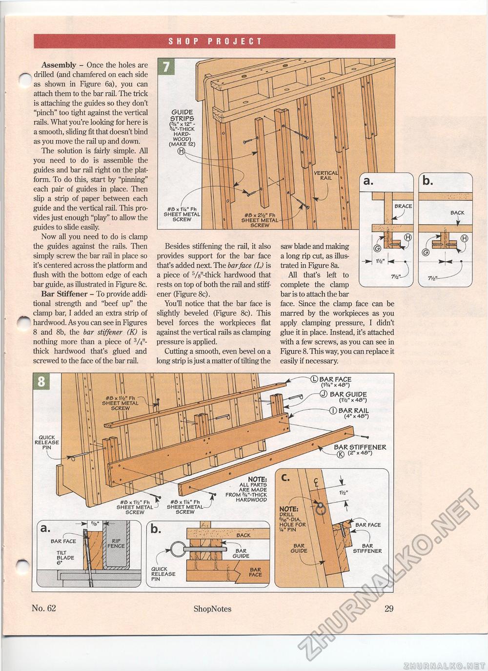
SHOP PROJECT Assembly - Once the holes are drilled (and chamfered on each side as shown in Figure 6a), you can attach them to the bar rail. The trick is attaching the guides so they don't "pinch" too tight against the vertical rails. What you're looking for here is a smooth, sliding fit that doesn't bind as you move the rail up and down. The solution is fairly simple. All you need to do is assemble the guides and bar rail right on the platform. To do this, start by "pinning" each pair of guides in place. Then slip a strip of paper between each guide and the vertical rail. This provides just enough "play" to allow the guides to slide easily. Now all you need to do is clamp the guides against the rails. Then simply screw the bar rail in place so it's centered across the platform and flush with the bottom edge of each bar guide, as illustrated in Figure 8c. Bar Stiffener - To provide additional strength and "beef up" the clamp bar, I added an extra strip of hardwood. As you can see in Figures 8 and 8b, the bar stiffener (K) is nothing more than a piece of W'-thick hardwood that's glued and screwed to the face of the bar rail. No. 62 ShopNotes 29 Besides stiffening the rail, it also provides support for the bar face that's added next. The bar face (L) is a piece of f>/8"-thick hardwood that rests on top of both the rail and stiffener (Figure 8c). You'll notice that the bar face is slightly beveled (Figure 8c). This bevel forces the workpieces flat against the vertical rails as clamping pressure is applied. Cutting a smooth, even bevel on a long strip is just a matter of tilting the w [•« 1 saw blade and making a long rip cut, as illustrated in Figure 8a. All that's left to complete the clamp bar is to attach the bar face. Since the clamp face can be marred by the workpieces as you apply clamping pressure, I didn't glue it in place. Instead, it's attached with a few screws, as you can see in Figure 8. This way, you can replace it easily if necessary. n>"—' GUIDE STRIPS /<" x 12" V-THICK HARDWOOD) (MAKE 12) e #6 x W Fh SHEET METAL SCREW BRACE QUICK RELEASE PIN BACK h l/L>r- , BAR GUIDE BAR FACE BAR FACE TILT BLADE & NOTE: DRILL 6/i6"-DIA. HOLE FOR 14" PIN BAR FACE BAR GUIDE BAR STIFFENER BAR STIFFENER (2" x 4S") NOTE: ALL PARTS ARE MADE FROM %"-THICK HARDWOOD BAR FACE (1%" X 4S") BAR GUIDE (W x 4&") BAR RAIL (4" x 4&") QUICK RELEASE SCREW |


