65 - Our Best Bench Yet, страница 15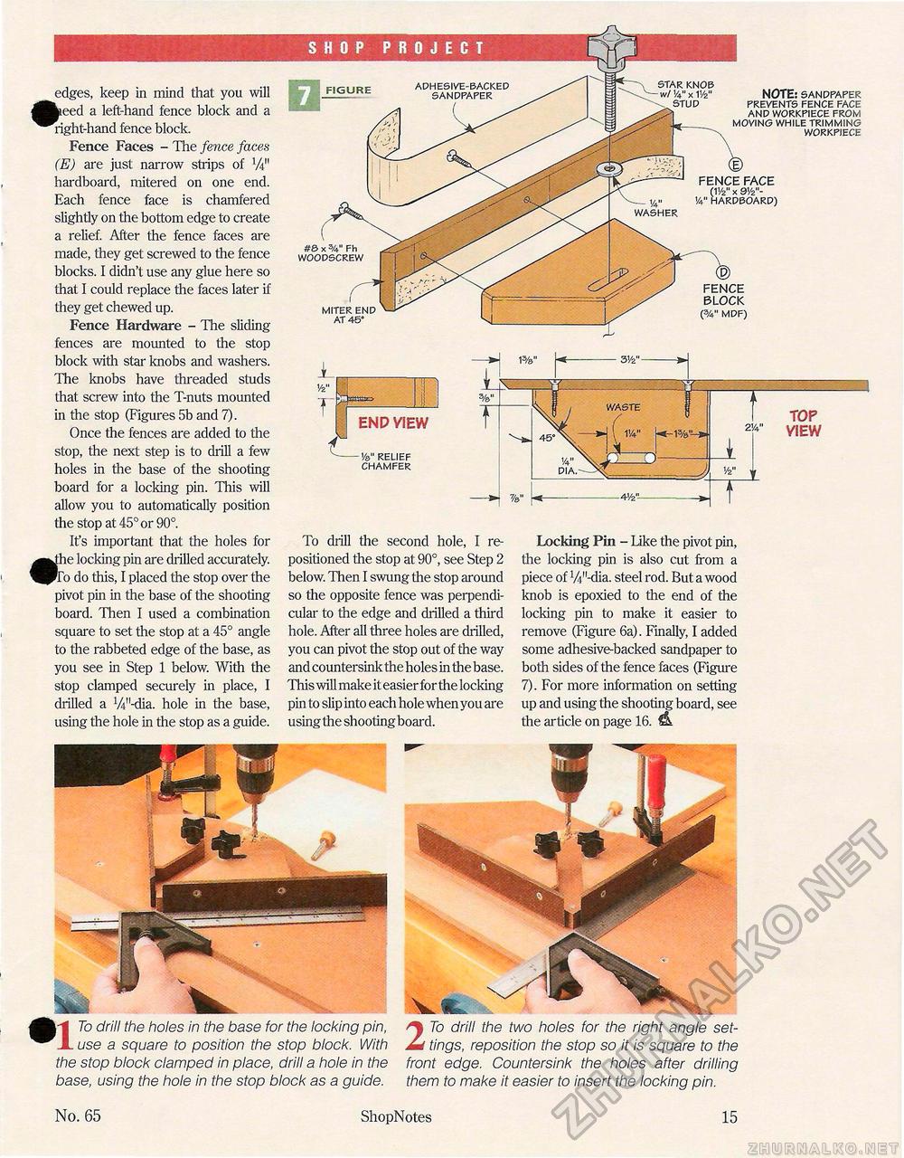
|"|| To drill the holes in the base for the locking pin, A use a square to position the stop block. With the stop block clamped in place, drill a hole in the base, using the hole in the stop block as a guide. 2 To drill the two holes for the right angle settings, reposition the stop so it is square to the front edge. Countersink the holes after drilling them to make it easier to insert the locking pin. edges, keep in mind that you will fl»eed a left-hand fence block and a ^bright-hand fence block. Fence Faces - The fence faces (E) are just narrow strips of W hardboard, mitered on one end. Each fence face is chamfered slightly on the bottom edge to create a relief. After the fence faces are made, they get screwed to the fence blocks. I didn't use any glue here so that I could replace the faces later if they get chewed up. Fence Hardware - The sliding fences are mounted to the stop block with star knobs and washers. The knobs have threaded studs that screw into the T-nuts mounted in the stop (Figures 5b and 7). Once the fences are added to the stop, the next step is to drill a few holes in the base of the shooting board for a locking pin. This will allow you to automatically position the stop at 45° or 90°. It's important that the holes for ^yhe locking pin are drilled accurately. ^To do this, I placed the stop over the pivot pin in the base of the shooting board. Then I used a combination square to set the stop at a 45° angle to the rabbeted edge of the base, as you see in Step 1 below. With the stop clamped securely in place, I drilled a W-dia. hole in the base, using the hole in the stop as a guide. To drill the second hole, I repositioned the stop at 90°, see Step 2 below. Then I swung the stop around so the opposite fence was perpendicular to the edge and drilled a third hole. After all three holes are drilled, you can pivot the stop out of the way and countersink the holes in the base. This will make iteasierfor the locking pin to slip into each hole when you are using the shooting board. Locking Pin - Like the pivot pin, the locking pin is also cut from a piece of W-dia. steel rod. But a wood knob is epoxied to the end of the locking pin to make it easier to remove (Figure 6a). Finally, I added some adhesive-backed sandpaper to both sides of the fence faces (Figure 7). For more information on setting up and using the shooting board, see the article on page 16. KNOB V4" X V/2" STUD NOTE: SANDPAPER PREVENTS FENCE FACE AND WORKPIECE FROM MOVING WHILE TRIMMING WORKPIECE FENCE FACE (1'/2" X 91/2"-y4" V4" HARDBOARD) WASHER FENCE BLOCK (3/4n MDF) FIGURE ADHESIVE-BAC SANDPAPEF MITER END AT 45° END VIEW C --------Ve>" RELIEF CHAMFER TOP VIEW #8 x Fh WOODSCREW WASTE 1 No. 65 ShopNotes 15 |


