91 - Planer Stand, страница 22
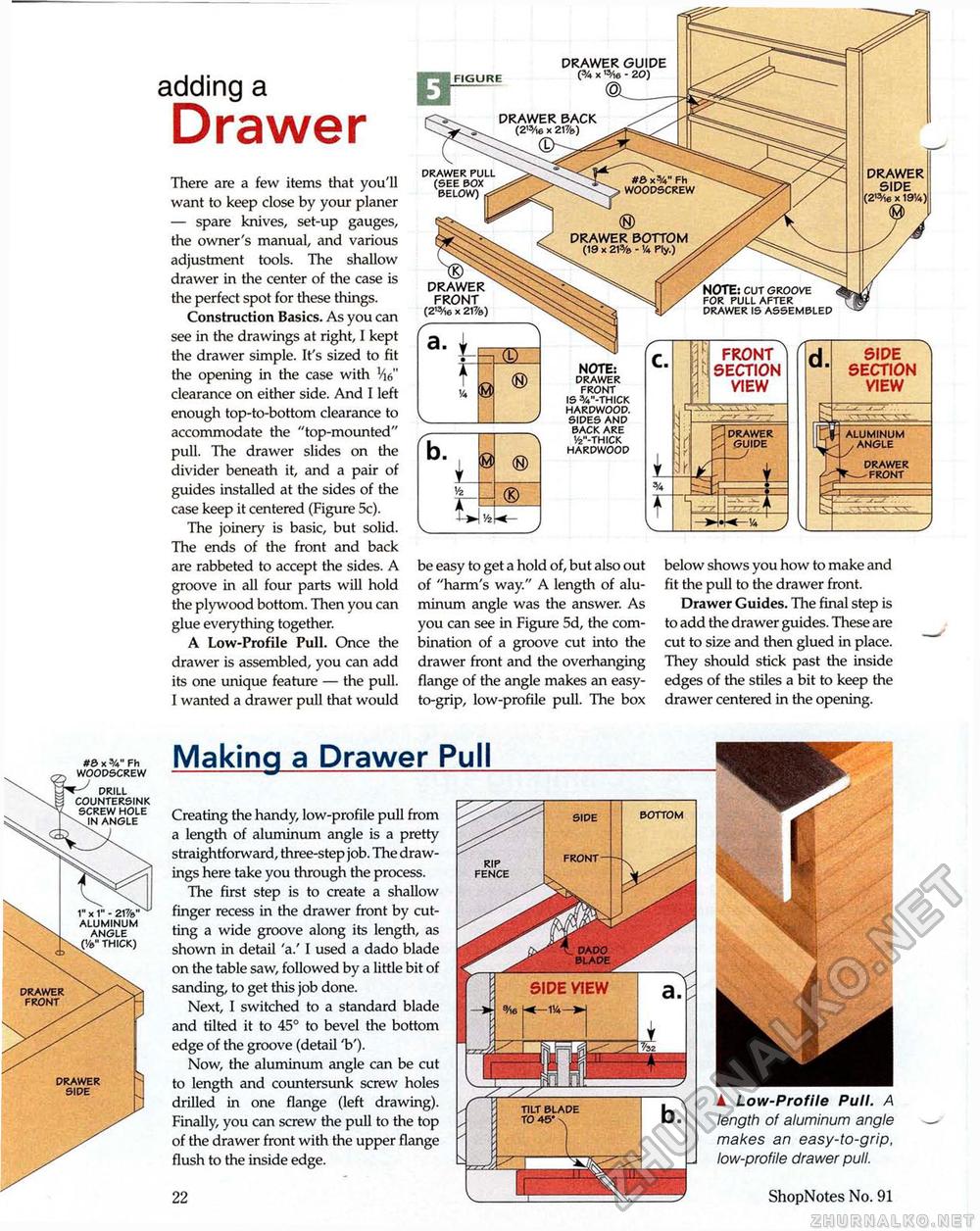
adding a Drawer There are a few items that you'll want to keep close by your planer — spare knives, set-up gauges, the owner's manual, and various adjustment tools. The shallow drawer in the center of the case is the perfect spot for these things. Construction Basics. As you can see in the drawings at right, I kept the drawer simple. It's sized to fit the opening in the case with 'V clearance on either side. And I left enough top-to-bottom clearance to accommodate the "top-mounted" pull. The drawer slides on the divider beneath it, and a pair of guides installed at the sides of the case keep it centered (Figure 5c). The joinery is basic, but solid. The ends of the front and back are rabbeted to accept the sides. A groove in all four parts will hold the plywood bottom. Then you can glue everything together. A Low-Profile Pull. Once the drawer is assembled, you can add its one unique feature — the pull. I wanted a drawer pull that would be easy to get a hold of, but also out of "harm's way." A length of aluminum angle was the answer. As you can see in Figure 5d, the combination of a groove cut into the drawer front and the overhanging flange of the angle makes an easy-to-grip, low-profile pull. The box below shows you how to make and fit the pull to the drawer front. Drawer Guides. The final step is to add the drawer guides. These are cut to size and then glued in place. They should stick past the inside edges of the stiles a bit to keep the drawer centered in the opening. A Low-Profile Pull. A length of aluminum angle makes an easy-to-grip, low-profile drawer pull. ShopNotes No. 91 Making a Drawer Pull Creating the handy, low-profile pull from a length of aluminum angle is a pretty straightforward, three-step job. The drawings here take you through the process. The first step is to create a shallow finger recess in the drawer front by cutting a wide groove along its length, as shown in detail 'a.' I used a dado blade on the table saw, followed by a little bit of sanding, to get this job done. Next, I switched to a standard blade and tilted it to 45° to bevel the bottom edge of the groove (detail 'b'). Now, the aluminum angle can be cut to length and countersunk screw holes drilled in one flange (left drawing). Finally, you can screw the pull to the top of the drawer front with the upper flange flush to the inside edge. 22 DRAWER PACK (2,3/i6 x 21%) DRAWER SIDE (2'Vie x 19'/*) #& x3/*" Fh WOODSCREW DRAWER BOTTOM (19 x 21% - '/* Ply.) NOTE: cut groove for pull after drawer is assembled FIGURE DRAWER GUIDE (% X ,5/ie - 20) drawer pull (see box below) , DRAWER FRONT (2'3/ie x 21%) FRONT SECTION VIEW DRAWER GUIDE
NOTE: drawer front is 3/v'-thick hardwood. sides and back are '/2"-thick hardwood |
||||||||||||||


