91 - Planer Stand, страница 24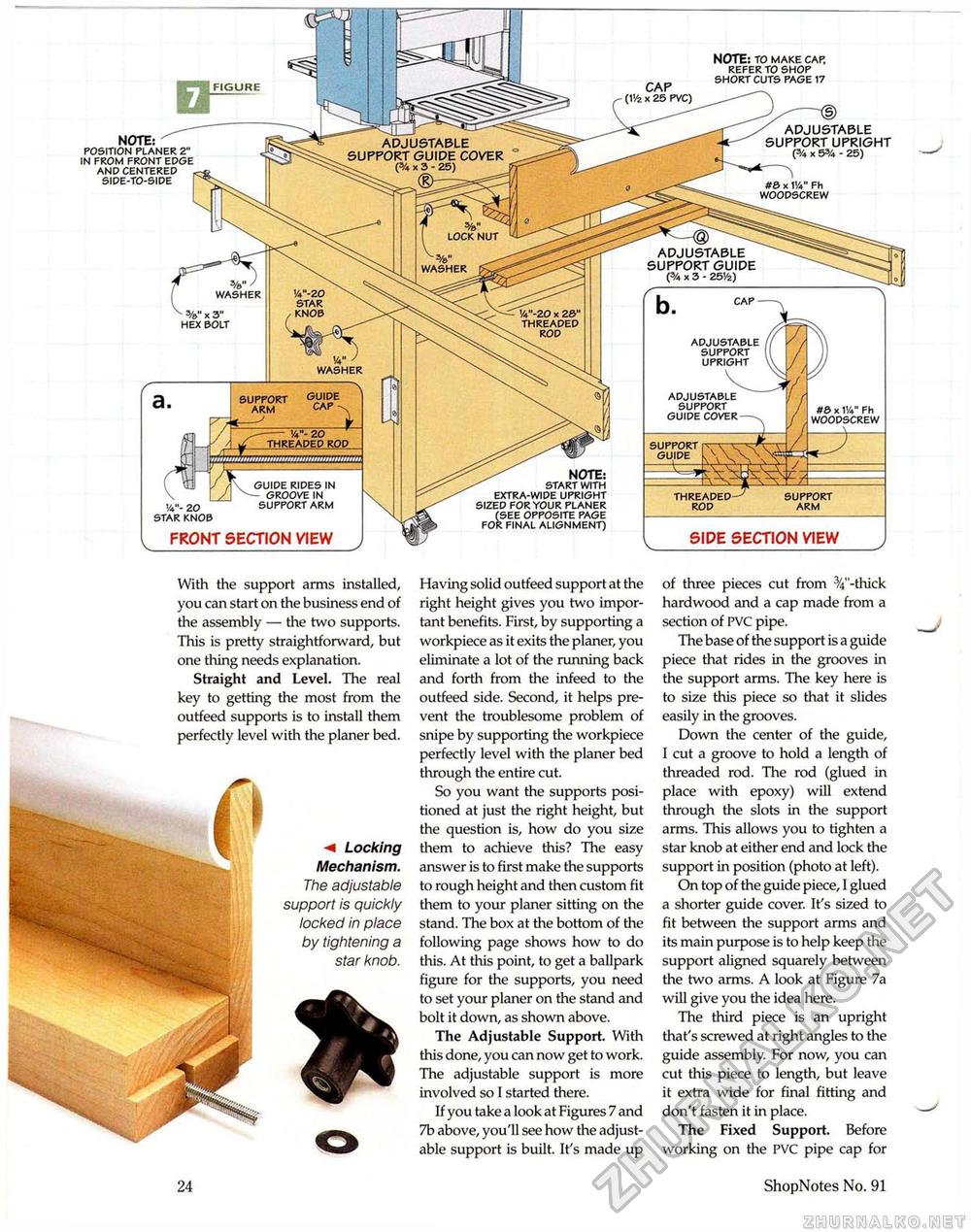
NOTE: POSITION PLANER 2" IN FROM FRONT EDGE AND CENTERED SIDE-TO-SIDE With the support arms installed, you can start on the business end of the assembly — the two supports. This is pretty straightforward, but one thing needs explanation. Straight and Level. The real key to getting the most from the outfeed supports is to install them perfectly level with the planer bed. m Locking Mechanism. The adjustable support is quickly locked in place by tightening a star knob. o 24 Having solid outfeed support at the right height gives you two important benefits. First, by supporting a workpiece as it exits the planer, you eliminate a lot of the running back and forth from the infeed to the outfeed side. Second, it helps prevent the troublesome problem of snipe by supporting the workpiece perfectly level with the planer bed through the entire cut. So you want the supports positioned at just the right height, but the question is, how do you size them to achieve this? The easy answer is to first make the supports to rough height and then custom fit them to your planer sitting on the stand. The box at the bottom of the following page shows how to do this. At this point, to get a ballpark figure for the supports, you need to set your planer on the stand and bolt it down, as shown above. The Adjustable Support. With this done, you can now get to work. The adjustable support is more involved so I started there. If you take a look at Figures 7 and 7b above, you'll see how the adjustable support is built. It's made up of three pieces cut from 34"-thick hardwood and a cap made from a section of PVC pipe. The base of the support is a guide piece that rides in the grooves in the support arms. The key here is to size this piece so that it slides easily in the grooves. Down the center of the guide, I cut a groove to hold a length of threaded rod. The rod (glued in place with epoxy) will extend through the slots in the support arms. This allows you to tighten a star knob at either end and lock the support in position (photo at left). On top of the guide piece, I glued a shorter guide cover. It's sized to fit between the support arms and its main purpose is to help keep the support aligned squarely between the two arms. A look at Figure 7a will give you the idea here. The third piece is an upright that's screwed at right angles to the guide assembly. For now, you can cut this piece to length, but leave it extra wide for final fitting and don't fasten it in place. The Fixed Support. Before working on the PVC pipe cap for ShopNotes No. 91 |


