91 - Planer Stand, страница 25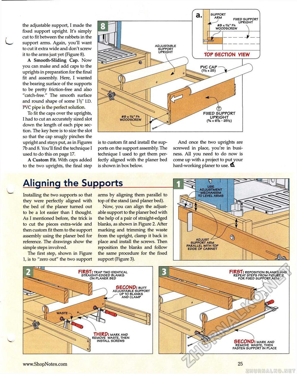
the adjustable support, I made the fixed support upright. It's simply cut to fit between the rabbets in the support arms. Again, you'll want to cut it extra wide and don't screw it to the arms just yet (Figure 8). A Smooth-Sliding Cap. Now you can make and add caps to the uprights in preparation for the final fit and assembly. Here, I wanted the bearing surface of the supports to be pretty friction-free and also "catch-free." The smooth surface and round shape of some W I.D. PVC pipe is the perfect solution. To fit the caps over the uprights, I had to cut an accurately sized slot down the length of each pipe section. The key here is to size the slot so that the cap snugly pinches the upright and stays put, as in Figures 7b and 8. You'll find the technique I used to do this on page 17. A Custom Fit. With caps added to the two uprights, the final step is to custom fit and install the supports on the support assembly. The technique I used to get them perfectly aligned with the planer bed is shown in box below. And once the two uprights are screwed in place, you're in business. All you need to do now is come up with a project to put your hard-working planer to use. fit Aligning the Supports Installing the two supports so that they were perfectly aligned with the bed of the planer turned out to be a lot easier than I thought. As I mentioned before, the trick is to cut the pieces extra-wide and then custom fit them to the support assembly using the planer bed for reference. The drawings show the simple steps involved. The first step, shown in Figure 1, is to "zero out" the two support arms by aligning them parallel to top of the stand (and planer bed). Now, you can align the adjustable support to the planer bed with the help of a pair of straight-edged blanks, as shown in Figure 2. After marking and trimming the waste from the upright, clamp it back in place and install the screws. Then reposition the blanks and follow the same procedure for the fixed support (Figure 3). ADJUST SUPPORT ARM PARALLEL WITH TOP EDGE OF CABINET SUPPORT ARM FIXED SUPPORT UPRIGHT #6 x W Fh WOODSCREW TOP SECTION VIEW FIXED SUPPORT UPRIGHT (5/4 x 67/» - 25V£) THIRD: mark and remove waste, then install screws FIRST: trap two identical straight-edged blanks on planer bed SECOND: butt adjustable support up to blanks and clamp FIRST: reposition blanks and repeat steps from figure 2 for fixed support arm SECOND: mark and remove waste, then fasten support in place 25 |


