91 - Planer Stand, страница 23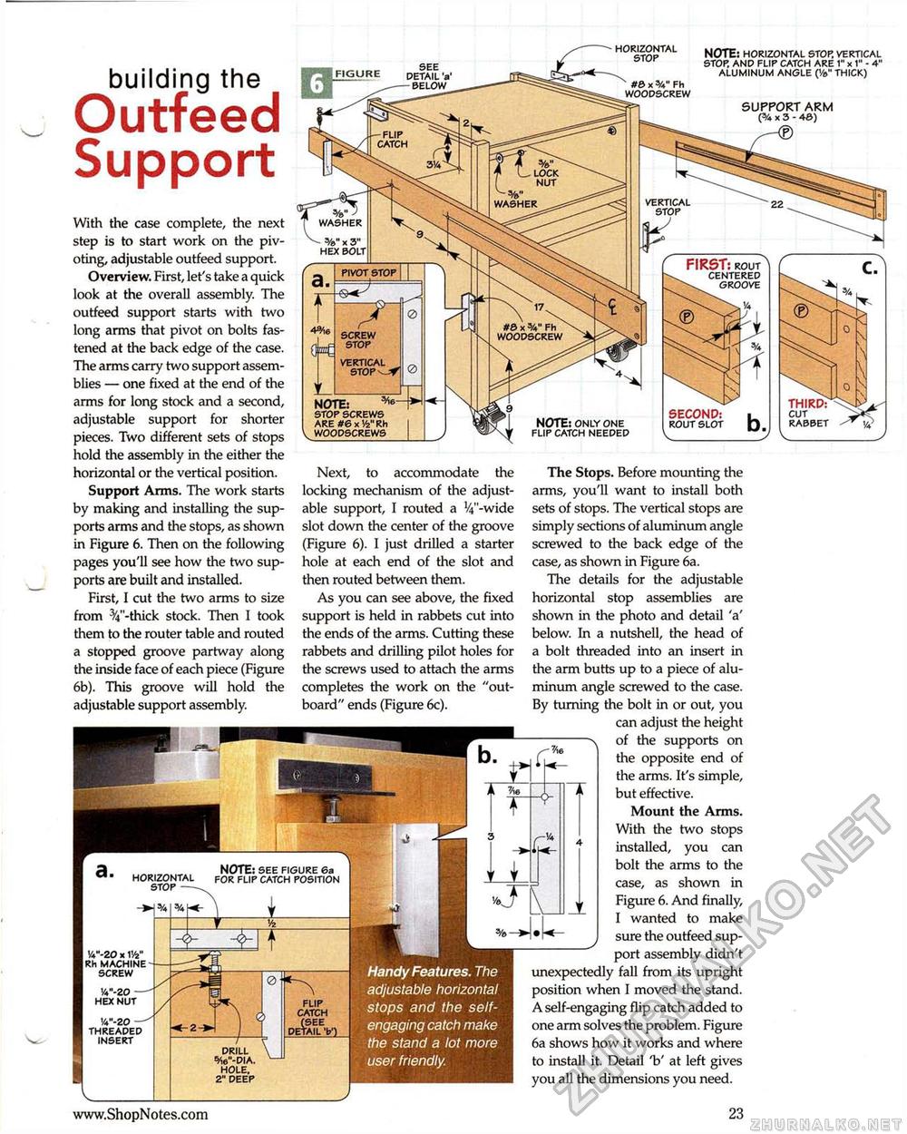
Handy Features. The adjustable horizontal stops and the self-engaging catch make the stand a lot more user friendly. HORIZONTAL STOP NOTE: HORIZONTAL STOP. VERTICAL STOP. AND FLIP CATCH ARE 1" * 1" - 4" ALUMINUM ANGLE (Ve" THICK) SEE DETAIL 'a' BELOW building the Outfeed Support" #e x Fh WOODSCREW SUPPORT ARM ('/« X 3 - 46) -FLIP CATCH LOCK NUT VERTICAL STOP WASHER %" J WASHER With the case complete, the next step is to start work on the pivoting, adjustable outfeed support. Overview. First, let's take a quick look at the overall assembly. The outfeed support starts with two long arms that pivot on bolts fastened at the back edge of the case. The arms carry two support assemblies — one fixed at the end of the arms for long stock and a second, adjustable support for shorter pieces. Two different sets of stops hold the assembly in the either the horizontal or the vertical position. Support Arms. The work starts by making and installing the supports arms and the stops, as shown in Figure 6. Then on the following pages you'll see how the two supports are built and installed. First, I cut the two arms to size from %"-thick stock. Then I took them to the router table and routed a stopped groove partway along the inside face of each piece (Figure 6b). This groove will hold the adjustable support assembly. FIRST: rout centered groove PIVOT stop #8 x Fh WOODSCREW VERTICAL STOV^Jf THIRD: CUT RABBET NOTE: * STOP SCREWS ARE #6x14" Rh WOODSCREWS SECOND: rout slot NOTE: ONLY ONE FLIP CATCH NEEDED Next, to accommodate the locking mechanism of the adjustable support, I routed a V^'-wide slot down the center of the groove (Figure 6). I just drilled a starter hole at each end of the slot and then routed between them. As you can see above, the fixed support is held in rabbets cut into the ends of the arms. Cutting these rabbets and drilling pilot holes for the screws used to attach the arms completes the work on the "outboard" ends (Figure 6c). The Stops. Before mounting the arms, you'll want to install both sets of stops. The vertical stops are simply sections of aluminum angle screwed to the back edge of the case, as shown in Figure 6a. The details for the adjustable horizontal stop assemblies are shown in the photo and detail 'a' below. In a nutshell, the head of a bolt threaded into an insert in the arm butts up to a piece of aluminum angle screwed to the case. By turning the bolt in or out, you can adjust the height ---n of the supports on CJ_ the opposite end of the arms. It's simple, _<[>- 11 but effective. Mount the Arms. With the two stops G- 4 installed, you can bolt the arms to the ycase, as shown in , f Figure 6. And finally, | I wanted to make J sure the outfeed support assembly didn't unexpectedly fall from its upright position when I moved the stand. A self-engaging flip catch added to one arm solves the problem. Figure 6a shows how it works and where to install it. Detail V at left gives you all the dimensions you need. NOTE: SEE FIGURE 6a FOR FLIP CATCH POSITION horizontal stop —■ •A"-20 x V/z" Rh MACHINE SCREW FLIP CATCH (SEE ETAIL 'b') W-ZO — THREADED INSERT DRILL W-DIA. HOLE. 2" DEEP |


