Woodworker's Journal 1993-17-1, страница 66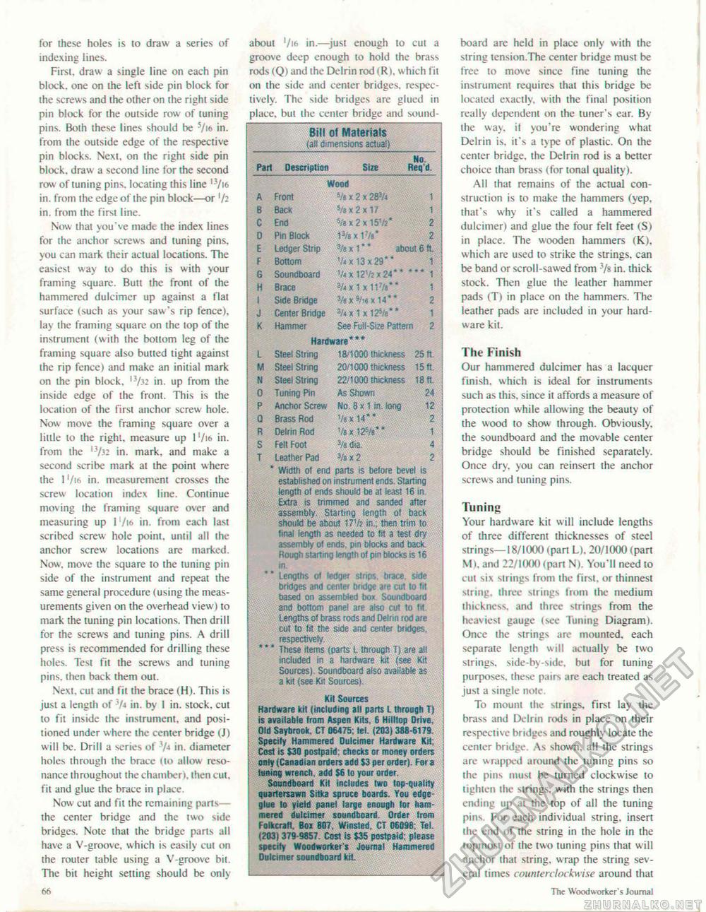
for these holes is to draw a series of indexing lines. First, draw a single line on each pin block, one on the left side pin block for the screws and the other on the right side pin block for the outside row of tuning pins. Both these lines should be s/if> in. from the outside edge of the respective pin blocks. Next, on the right side pin block, draw a second line for the second row of tuning pins, locating this line l3/i6 in. from the edge of the pin block—or '/2 in. from the first line. Now that you've made the index lines for the anchor screws and tuning pins, you can mark their actual locations. The easiest way to do this is with your framing square. Butt the front of the hammered dulcimer up against a flat surface (such as your saw's rip fence), lay the framing square on the top of the instrument (with the bottom leg of the framing square also butted tight against the rip fence) and make an initial mark on the pin block. 13/32 in. up from the inside edge of the front. This is the location of the first anchor screw hole. Now move the framing square over a little to the right, measure up I ,/i<> in. from the ,3/32 in. mark, and make a second scribe mark at the point where the 1 Vies in. measurement crosses the screw location index line. Continue moving the framing square over and measuring up l'/us. in. from each last scribed screw hole point, until all the anchor screw locations are marked. Now. move the square to the tuning pin side of the instrument and repeat the same general procedure (using the measurements given on the overhead view) to mark the tuning pin locations. Then drill for the screws and tuning pins. A drill press is recommended for drilling these holes. Test fit the screws and tuning pins, then back them out. Next, cut and fit the brace (H). This is just a length of JA» in. by 1 in. stock, cut to fit inside the instrument, and positioned under where ihe center bridge (J) will be. Drill a series of 7< in. diameter holes through the brace ilo allow resonance throughout the chamber), (hen cut. fit and glue the brace in place. Now cut and fit the remaining parts— the center bridge and the two side bridges. Note that the bridge parts all have a V-groove. which is easily cut on the router table using a V-groove bit. The bit height setting should be only IX about '/16 in.—just enough to cul a groove deep enough to hold the brass rods (Q) and the Delrin rod (R). which fit on the side and center bridges, respectively. The side bridges are glued in place, bul the center bridge and sound- Bill of Materials (all dimensions actual) Part Description Size No. Req d. Wood 5/b x 2 x 283/4 i s/8 x 2 x 17 | 5/ex 2 x 151/2* 13/8 x 1v 3/e x 1* * about 6 ft. V* x 13 x 29* * i 5/4Xl2'/2X24** *** 1 */4x1X11V 1 #t*!«x14*' 2 A Front B Back C End D Pin Block £ Ledger Strip F Bottom G Soundboard H Brace I Side Bridge J Center Bridge 3/< x 1 x 125/a** 1 K Hammer See Full-Size Pattern 2 Hardware*** L Steel String 18/1000 thickness 25 ft M Steel String 20/1000 thickness 15 ft. N Steel String 22/1000 thickness 18 ft 0 Tuning Pin As Shown 24 P Anchor Screw No. 8 x 11n. long 12 Q Brass Rod Vsxl4** 2 R Delrin Rod V*x 125/6*" 1 S Felt Foot 3/a dia 4 T Leather Pad 3/b x 2 2 * Width ol end parts is before bevel is established on instrument ends. Starting length o( ends should be at least 16 in Extra is trimmed and sanded after assembly. Starting length of back shook! be about 17V? in., then trim to final length as needed to fit a test dry assembly of ends, pin blocks and back. Rough starting length of pin blocks is 16 in. * * Lengths o< ledger strips, brace side bridges and center bodge are cut to fit based on assembled box Soundboard and bottom panel are also cut to lit Lengths of brass rods and Delrin rod are cut to tit the side and center bndges. respectively * * * These items (parts L through T) are all included in a hardware kit (see Kit Sources). Soundboard also available as a kit (see Kit Sources) Kit Sources Hardware kit (including all parts L through T) is available from Aspen Kits. 6 Hilltop Drive. Old Saybrook. CT 06475; tel. (203) 388-6179. Specify Hammered Dulcimer Hardware Kit: Cost is $30 postpaid, checks or money orders only (Canadian orders add S3 per order). For a tuning wrench, add $6 to your order. Soundboard Kit includes two (op-quality quartersawn Sitka spruce boards. You edge glue lo yield panel large enough for hammered dulcimer soundboard. Order tram f oikcraft. Box 807, Winsted. CT 06098: Tel. (203) 379-9857. Cost is $35 postpaid: please specify Woodworker's Journal Hammered Oulcimer soundboard kiL board are held in place only with the string tension.The center bridge must be free to move since fine tuning the instrument requires that this bridge be located exactly, with the final position really dependent on the tuner's ear. By the way, it you're wondering what Delrin is, it's a type of plastic. On the center bridge, the Delrin rod is a better choice than brass (for tonal quality). All that remains of the actual construction is to make the hammers (yep, that's why it's called a hammered dulcimer) and glue the four felt feet (S) in place. The wooden hammers (K), which are used to strike the strings, can be band or scroll-sawed from ?/s in. thick stock. Then glue the leather hammer pads (T) in place on the hammers. The leather pads are included in your hardware kit. The Finish Our hammered dulcimer has a lacquer finish, which is ideal for instruments such as this, since it affords a measure of protection while allow ing the beauty of the wood to show through. Obviously, the soundboard and the movable center bridge should be finished separately. Once dry, you can reinsert the anchor screws and tuning pins. Tuning Your hardware kit will include lengths of three different thicknesses of steel strings— 18/1000 (pan L). 20/1000 (part M), and 22/1000 (part N). You'll need to cut six strings from the firsi. or thinnest string, three strings from the medium thickness, and three strings from the heaviest gauge (see Tuning Diagram). Once the strings are mounted, each separate length will actually be two strings, side-by-side, but for tuning purposes, these pairs are each treated as just a single note. To mount the strings, first lay the brass and Delrin rods in place on their respective bridges and roughly locate the center bridge. As shown, all the strings are wrapped around the tuning pins so the pins must be turned clockwise to tighten the strings, with the strings then ending up ai the top of all the tuning pins. For each individual string, insert the end of the string in the hole in the topmost of the two tuning pins that w ill anchor that string, wrap the string several times counterclockwise around that The Woodworker'1, Journal |


