Woodworker's Journal 1994-18-3, страница 40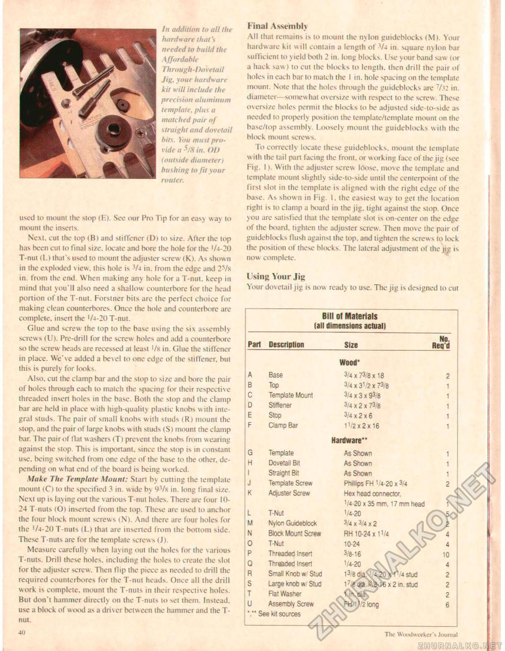
In addition to all the hardware that's needed to build the Affordable Th rough-Do retail Jig, your hardware kit will include the precision aluminum template, plus a matched pair of straight and dovetail hits. You must provide a S/H in. Ol) (outside diumeter) hushing to Jit your router. used lo mount ihe stop (E). See our Pro Tip for an easy way to mount the inserts. Next, cut the top (B> and stiffener (D) to size. After the lop has been cut to final size, locate and bore ihe hole for the 1A-20 T-nut (L) that's used to mount the adjuster screw (K). As shown in the exploded view, litis hole is 3/4 in. from ihe edge and 2-Vs in. from the end. When making any hole for a T-nut. keep in mind that you'll also need a shallow counterbore for the head portion of the T-nut. Forstner bits are the perfect choice for making clean counterbores. Once the hole and counterbore are complete, insert the '/4-20 T-nui. Glue and screw ihe lop lo the base using ihe six assembly screws (U). Pre-drill for the screw holes and add a counterbore so ihe screw heads are recessed at leasi 1 /s in. Glue ihe stiffener in place. We've added a bevel to one edge of the stiffener. but this is purely for looks. Also, cut the clamp bar and the stop to size and bore the pair of holes through each lo match the spacing for their respective threaded insert holes in the base. Both ihe stop and ihe clamp bar arc held in place w ith high-quality plastic knobs with integral studs. The pair of small knobs w ilh sluds (Rj mount the stop, and the pair of large knobs with studs (S) mount the clamp bar. The pair of flat w ashers (T) prevent the knobs from w earing against the stop This is important, since the stop is in constant use. being switched from one edge of the base to the other, depending on w hat end of the board is being worked. Make The Template Mount: Start by cutting the template mount (C) to the specified 3 in. wide by 97k in. long final size. Next up is laying out the various T-nul holes. There are four 1024 T-nuts (Oi inserted from the top. These are used lo anchor the lour block mount screw s (N). And there are four holes for the '/4-20 T-nuts (L) that are inserted from the bottom side. These T-nuts are for the template screws tJ). Measure carefully when laying out ihe holes for the various T-nuts. Drill these holes, including the holes to create ihe slot for the adjuster screw. Then flip the piece as needed to drill the required counterbores for the T-nut heads. Once all the drill work is complete, mount the T-nuts in their respective holes. Bui don't hammer directly on the T-nuts to set them. Instead, use a block of wood as a driv er betw een the hammer and the T-nut. 23 Final Assembly All that remains is to mount the ny Ion guideblocks (M). Your hardware kit will contain a length of 74 in. square nylon bar sufficient to yield both 2 in. long blocks. Use your band saw (or a hack saw) to cut the blocks to length, then drill the pair of holes in each bar to match the I in. hole spacing on ihe template mount. Note that the holes through the guideblocks arc 7/j2 in. diameter—somew hat oversize w ith respect to the screw. These oversize holes permit the blocks to be adjusted side-lo-side as needed to properly position the template/template mount on the base/top assembly. Loosely mount the guideblocks with the block mount screws. To correctly locate these guideblocks. mount the template w ith the tail part facing the front, or working face of the jig (see Fig. I). With ihe adjuster screw loose, move the template and template mount slightly side-to-side until ihe centerpoint of the first sloi in the template is aligned with the right edge of the base. As shown in Fig. 1. the easiest way to gel ihe location right is to clamp a board in the jig, tight against the slop. Once you are satisfied lhat the template slot is on-center on ihe edge of the board, tighten the adjuster screw. Then move the pair of guideblocks flush against the top. and tighten the screws to lock the position of these blocks. The lateral adjustment of the |ig is now complete. Using Your Jig Your dovetail jig is now ready to use. The jig is designed lo cut Bill of Materials (all dimensions actual)
'." See kit sources '." See kit sources The Woodw orker's Journal |


