Woodworker's Journal 2004-28-6, страница 29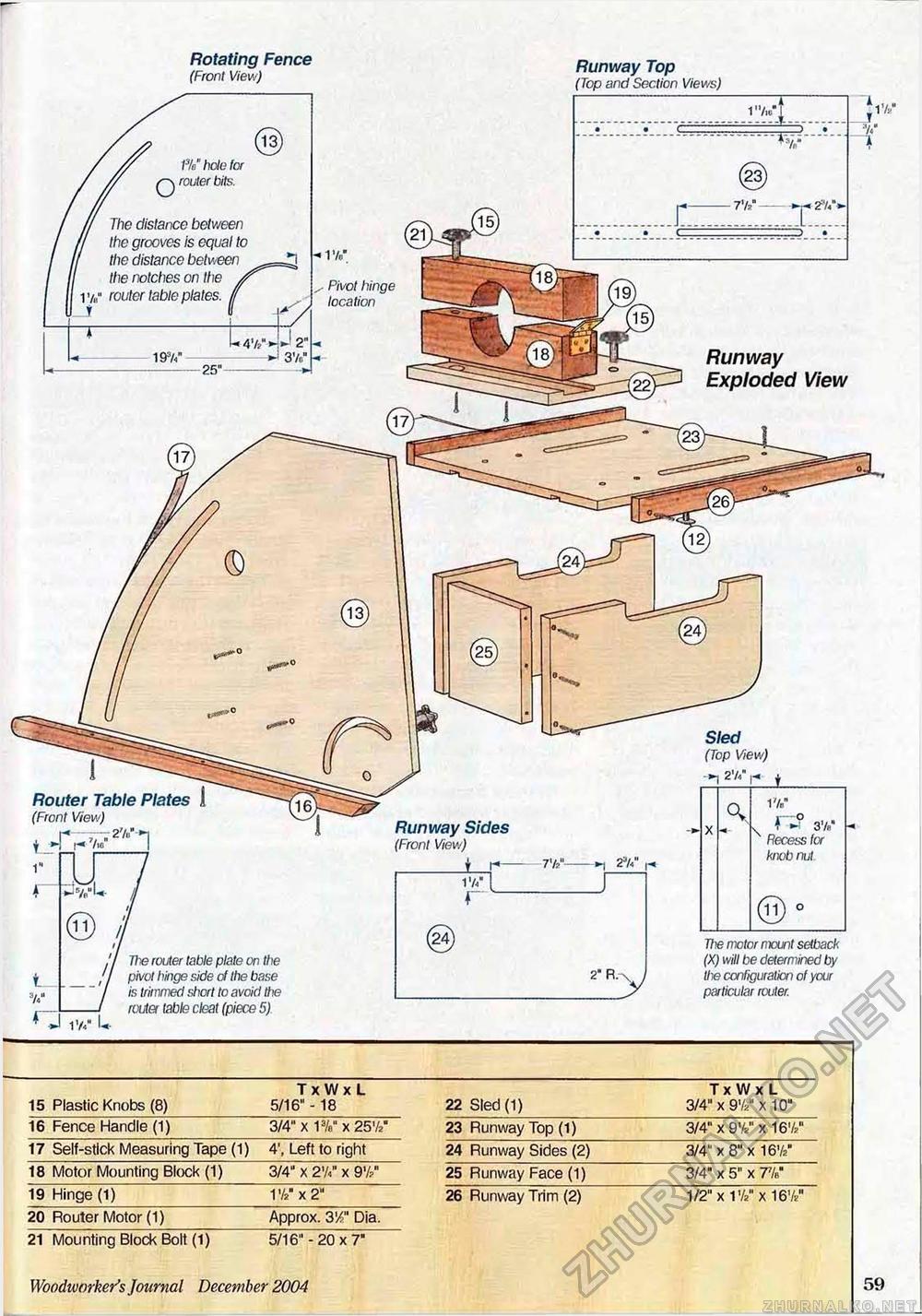
/%" hole for router bits. H The distance between ' the grooves is equal to the distance between the notches on the y 1 v„" router table plates. (( Pivot hinge location Runway Exploded View Router Table Plates 1 (Front View) - — 27«."-*i Runway Sides (Front View) t 3V« Recess for knob nut The motor mount setback (X) will be determined by the configuration of your particular router. The router table plate on the pivot hinge side of the base is trimmed i^hcrt to avoid the router table cleat (piece 5) Rotating Fence Ru T (Front View) and Section Views)
21 Mounting Block Bolt (1) 5/16" -20x7" 21 Mounting Block Bolt (1) 5/16" -20x7" Woodworker's Journal Decernber 2004 59 |


