Woodworker's Journal 2004-28-6, страница 31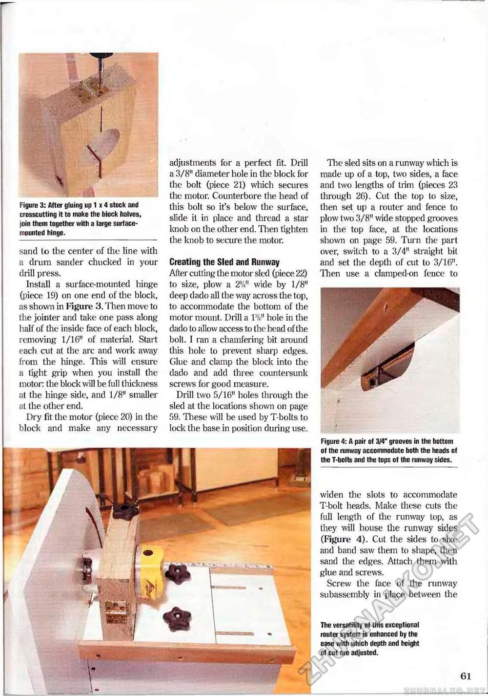
Figure 3: After gluing up 1 x 4 stock and crosscutting it to make the biock halves, join them together with a large surface-mounted hinge. sand Lo the center of the line with a drum sander chucked in your drill press. Install a surface-mounted hinge (piece 19) on one end of the block, as shown in Figure 3. Then move to the jointer and take one pass along half of the inside face of each block, removing 1/16" of material. Start each cut a( the arc and work away from the hinge. This will ensure a tight grip when you install the motor: the block will be full thickness at the hinge side, and 1/8" smaller at the other end. Dry fit the motor (piece 20) in the block and make any necessary adjustments for a perfect fit. Drill a 3/8" diameter hole in the block for the bolt (piece 21) which secures the motor. Counterbore the head of this bolt so it's below the surface, slide it in place and thread a star knob on the other end. Then tighten the knob to secure the motor. Creating the Sled and Runway After cutting the motor sled (piece 22) to size, plow a 2Vi" wide by 1/8" deep dado all the way across the top, to accommodate the bottom of the motor mount. Drill a IV hole in the dado lo allow access to the head of the bolt. I ran a chamfering bit around this hole lo prevent sharp edges. Glue and clamp the block into the dado and add three countersunk screws for good measure. Drill two 5/16" holes through the sled at the locations shown on page 59. These will be used by Tbolts to lock the base in position during use. The sled sits on a runway wliich is made up of a top, two sides, a face and two lengths of trim (pieces 23 through 26). Cut the top to size, then set up a router and fence to plow two 3/8" wide stopped grooves in the top face, al the locations shown on page 59. Turn the part over, switch to a 3/4" straight bil and set the depth of cut to 3/16". Then use a clamped-on fence to Figure 4: A pair of 3/4" grooves in the bottom of the runway accommodate both the heads of the T-bolts and the tops of the runway sides. widen the slots to accommodate T-bolt heads. Make these cuts the full length of the runway top, as they will house the runway sides (Figure 4). Cut the sides to size and band saw them to shape, then sand the edges. Attach them with glue and screws. Screw the face of Lhe runway subassembly in place between the The versatility of this exceptional router system is enhanced by the ease with which depth and height of cut are adjusted. 61 |


