Woodworker's Journal 2006-30-2, страница 28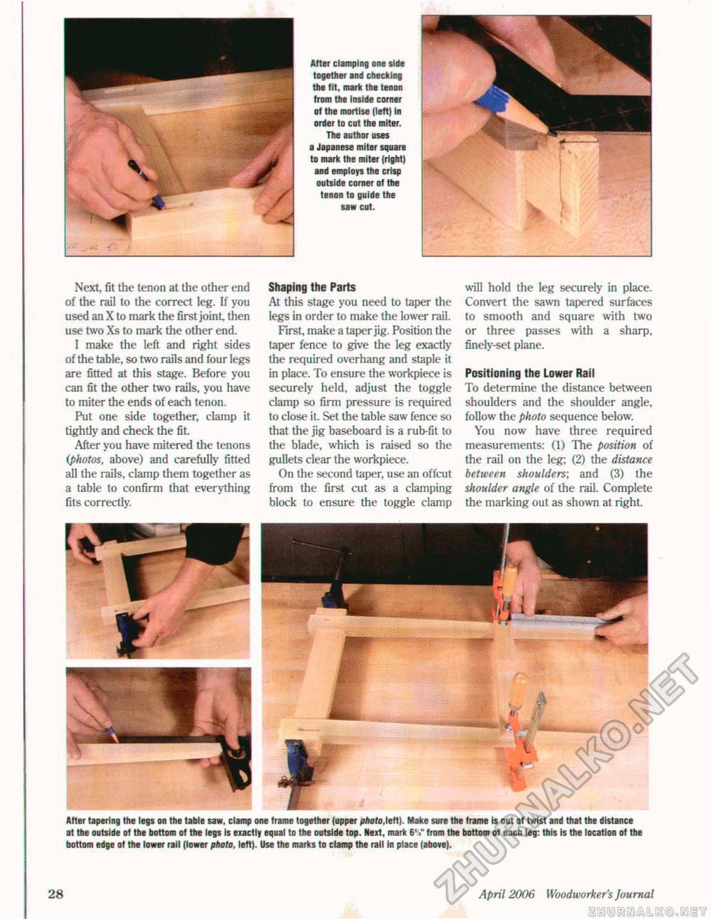
After clamping one side together and checking the fit, mark the tenon from the inside corner of the mortise (left) in order to cut the miter. The author uses a Japanese miter square to mark the miter (right) and employs the crisp outside corner of the tenon to guide the saw cut. Next fit the tenon at the other end of the rail to the correct leg. If you used an X to mark the first joint, then use two Xs to mark the other end. I make the left and right sides of the table, so two rails and four legs are fitted at this stage. Before you can fit the other two rails, you have to miter the ends of each tenon. Put one side together, clamp it tightly and check the fit. After you have mitered the tenons (photos, above) and carefully fitted all the rails, clamp them together as a table to confirm that everything fits correctly. Shaping the Parts At this stage you need to taper the legs in order to make the lower rail. First, make a taper jig. Position the taper fence to give the leg exactly the required overhang and staple it in place. To ensure the workpiece is securely held, adjust the toggle clamp so firm pressure is required to close it. Set the table saw fence so that the jig baseboard is a rub-fit to the blade, which is raised so the gullets clear the workpiece. On the second taper, use an offcut from the first cut as a clamping block to ensure the toggle clamp will hold the leg securely in place. Convert the sawn tapered surfaces to smooth and square with two or three passes with a sharp, finely-set plane. Positioning the Lower Rail To determine the distance between shoulders and the shoulder angle, follow the photo sequence below. You now have three required measurements: (1) The position of the rail on the leg; (2) the distance between shoulders; and (3) the shoulder angle of the rail. Complete the marking out as shown at right. After tapering the legs on the table saw, clamp one frame together (upper photo,left). Make sure the frame is out of twist and that the distance at the outside of the bottom of the legs is exactly equal to the outside top. Next, mark 6V from the bottom of each leg: this is the location of the bottom edge of the lower rail (lower photo, left). Use the marks to clamp the rail in place (above). 28 April 2006 Woodworker's Journal |


