Popular Woodworking 2007-11 № 165, страница 70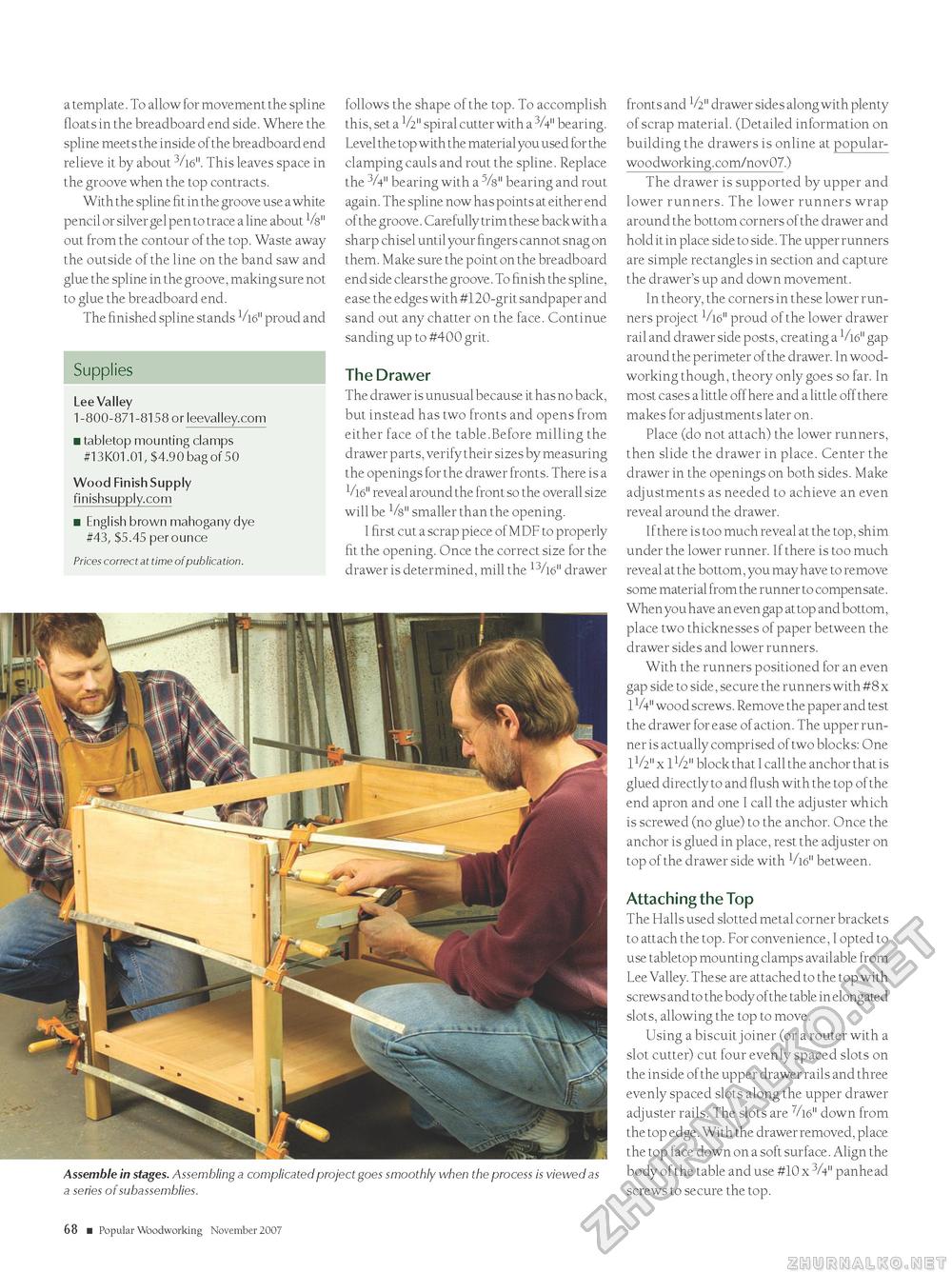
a template. To allow for movement the spline floats in the breadboard end side. Where the spline meets the inside of the breadboard end relieve it by about 3/l6". This leaves space in the groove when the top contracts. With the spline fit in the groove use a white pencil or silver gel pen to trace a line about Vs" out from the contour of the top. Waste away the outside of the line on the band saw and glue the spline in the groove, making sure not to glue the breadboard end. The finished spline stands V16" proud and follows the shape of the top. To accomplish this, set a V2" spiral cutter with a 3A" bearing. Level the top with the material you used for the clamping cauls and rout the spline. Replace the 3A" bearing with a 5A" bearing and rout again. The spline now has points at either end of the groove. Carefully trim these back with a sharp chisel until your fingers cannot snag on them. Make sure the point on the breadboard end side clears the groove. To finish the spline, ease the edges with #120-grit sandpaper and sand out any chatter on the face. Continue sanding up to #400 grit. The Drawer The drawer is unusual because it has no back, but instead has two fronts and opens from either face of the table.Before milling the drawer parts, verify their sizes by measuring the openings for the drawer fronts. There is a V16" reveal around the front so the overall size will be 1/s" smaller than the opening. I first cut a scrap piece of MDF to properly fit the opening. Once the correct size for the drawer is determined, mill the 13/16" drawer Supplies Lee Valley 1-800-871-8158 or leevalley.com ■ tabletop mounting clamps #13K01.01, $4.90 bag of 50 Wood Finish Supply finishsupply.com ■ English brown mahogany dye #43, $5.45 per ounce Prices correct at time of publication. Assemble in stages. Assembling a complicated project goes smoothly when the process is viewed as a series of subassemblies. fronts and V2" drawer sides along with plenty of scrap material. (Detailed information on building the drawers is online at popular-woodworking.com/nov07.) The drawer is supported by upper and lower runners. The lower runners wrap around the bottom corners of the drawer and hold it in place side to side. The upper runners are simple rectangles in section and capture the drawer's up and down movement. In theory, the corners in these lower runners project V16" proud of the lower drawer rail and drawer side posts, creating a V16" gap around the perimeter of the drawer. In woodworking though, theory only goes so far. In most cases a little off here and a little off there makes for adjustments later on. Place (do not attach) the lower runners, then slide the drawer in place. Center the drawer in the openings on both sides. Make adjustments as needed to achieve an even reveal around the drawer. If there is too much reveal at the top, shim under the lower runner. If there is too much reveal at the bottom, you may have to remove some material from the runner to compensate. When you have an even gap at top and bottom, place two thicknesses of paper between the drawer sides and lower runners. With the runners positioned for an even gap side to side, secure the runners with #8 x 1V4" wood screws. Remove the paper and test the drawer for ease of action. The upper runner is actually comprised of two blocks: One 1V>" x 1V2" block that I call the anchor that is glued directly to and flush with the top of the end apron and one I call the adjuster which is screwed (no glue) to the anchor. Once the anchor is glued in place, rest the adjuster on top of the drawer side with V16" between. Attaching the Top The Halls used slotted metal corner brackets to attach the top. For convenience, I opted to use tabletop mounting clamps available from Lee Valley. These are attached to the top with screws and to the body of the table in elongated slots, allowing the top to move. Using a biscuit joiner (or a router with a slot cutter) cut four evenly spaced slots on the inside of the upper drawer rails and three evenly spaced slots along the upper drawer adjuster rails. The slots are V16" down from the top edge. With the drawer removed, place the top face down on a soft surface. Align the body of the table and use #10 x 3A" panhead screws to secure the top. 68 ■ Popular Woodworking November 2007 |


