15 - Sliding Table, страница 21
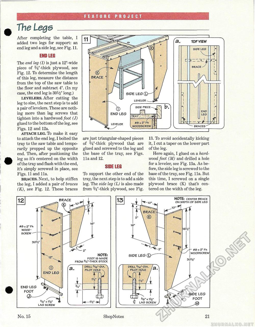
FEATURE PROJECT The Lege_ After completing the table, I added two legs for support: an end leg and a side leg, see Fig. 11. EMD LEO The end leg (I) is just a 12"-wide piece of 3/4"-thick plywood, see Fig. 12. To determine the length of this leg, measure the distance from the top of the saw table to the floor and subtract 4". (In my case, the end leg is 3OV2" long.) levelers. After cutting the leg to size, the next step is to add a pair of levelers. These are nothing more than lag screws that tighten into a hardwood foot (J) glued to the bottom of the leg, see Figs. 12 and 12a. attach leg. To make it easy to attach the end leg, I bolted the tray to the saw table and temporarily propped up the opposite end. Then, after positioning the leg so it's centered on the width of the tray and flush with the end, it's simply screwed in place, see Figs. 11 and 11a. braces. Next, to help stiffen the leg, I added a pair of braces (K), see Fig. 12. These braces are just triangular-shaped pieces of 3/4"-thick plywood that are glued and screwed to the leg and the base of the tray, see Figs. 11a and 12. SIDE LEO To support the other end of the tray, the next step is to add a side leg. The side leg (L) is also made from 3/4"-thick plywood, see Fig. 13. To avoid accidentally kicking it, I cut a taper on the lower part of the leg. Here again, I glued on a hardwood, foot (M) and drilled a hole for a leveler, see Fig. 13a. As before, the side leg is screwed to the base of the tray, see Fig. 11a. But this time, I screwed on a single plywood brace (K) that's centered on the width of the leg. No. 15 ShopNotes 21 |


