15 - Sliding Table, страница 19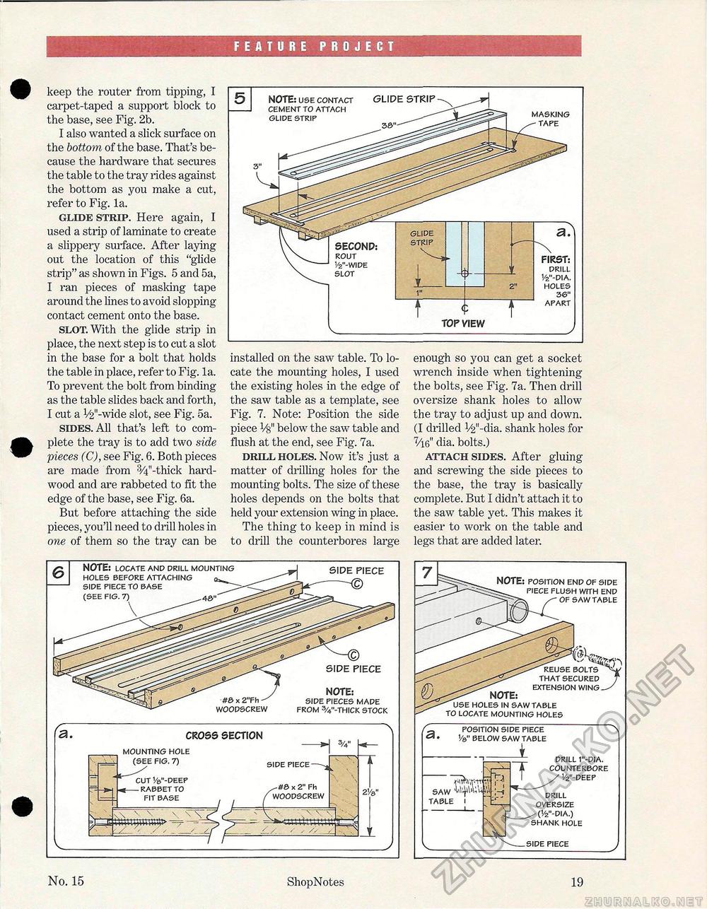
FEATURE PROJECT keep the router from tipping, I carpet-taped a support block to the base, see Fig. 2b. I also wanted a slick surface on the bottom of the base. That's because the hardware that secures the table to the tray rides against the bottom as you make a cut, refer to Fig. la. glide strip. Here again, I used a strip of laminate to create a slippery surface. After laying out the location of this "glide strip" as shown in Figs. 5 and 5a, I ran pieces of masking tape around the lines to avoid slopping contact cement onto the base. slot. With the glide strip in place, the next step is to cut a slot in the base for a bolt that holds the table in place, refer to Fig. 1a.. To prevent the bolt from binding as the table slides back and forth, I cut a V2"-wide slot, see Fig. 5a. sides. All that's left to complete the tray is to add two side pieces (C), see Fig. 6. Both pieces are made from 3/4"-thick hardwood and are rabbeted to fit the edge of the base, see Fig. 6a. But before attaching the side pieces, you'll need to drill holes in one of them so the tray can be installed on the saw table. To locate the mounting holes, I used the existing holes in the edge of the saw table as a template, see Fig. 7. Note: Position the side piece Vg" below the saw table and flush at the end, see Fig. 7a. drill holes. Now it's just a matter of drilling holes for the mounting bolts. The size of these holes depends on the bolts that held your extension wing in place. The thing to keep in mind is to drill the counterbores large enough so you can get a socket wrench inside when tightening the bolts, see Fig. 7a. Then drill oversize shank holes to allow the tray to adjust up and down. (I drilled V2"-dia. shank holes for 7/i6" dia. bolts.) attach sides. After gluing and screwing the side pieces to the base, the tray is basically complete. But I didn't attach it to the saw table yet. This makes it easier to work on the table and legs that are added later. FIRST: drill 1/2"-dia. holes 36" apart masking tape SECOND: rout 1/2"-wide slot <P TOP VIEW NOTE: use contact cement to attach glide strip GLIDE STRIP GLIDE STRIP SIDE PIECE SIDE PIECE CROSS SECTION MOUNTING HOLE FIG. 7) :uT V-DEEP RABBET TO FIT RA^F SIDE PIECE x 2" Fh woodscrew NOTE: locate and drill mounting holes before attaching side piece to base (see fig. 7) woodscrew NOTE: side pieces made from 3/4"-thick stock NOTE: position end of side piece flush with end of saw table reuse bolts that secured j extension wing—' NOTE: use holes in saw table to locate mounting holes position side piece v&" below saw table saw table drill 1"-dia. counterbore 1/2"-deep drill oversize (1/2"-dia.) shank hole side piece No. 15 ShopNotes 19 |


