15 - Sliding Table, страница 20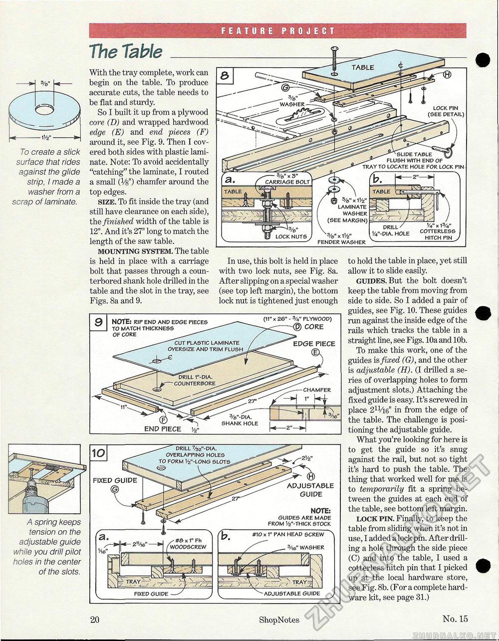
FEATURE PROJECT To create a slick surface that rides against the glide strip, I made a washer from a scrap of laminate. The Table With the tray complete, work can begin on the table. To produce accurate cuts, the table needs to be flat and sturdy. So I built it up from a plywood core (D) and wrapped hardwood edge (E) and end pieces (F) around it, see Fig. 9. Then I covered both sides with plastic laminate. Note: To avoid accidentally "catching" the laminate, I routed a small (Vg") chamfer around the top edges. size. To fit inside the tray (and still have clearance on each side), the finished width of the table is 12". And it's 27" long to match the length of the saw table. mounting system. The table is held in place with a carriage bolt that passes through a coun-terbored shank hole drilled in the table and the slot in the tray, see Figs. 8a and 9. A spring keeps tension on the adjustable guide while you drill pilot holes in the center of the slots. In use, this bolt is held in place with two lock nuts, see Fig. 8a. After slipping on a special washer (see top left margin), the bottom lock nut is tightened just enough to hold the table in place, yet still allow it to slide easily. guides. But the bolt doesn't keep the table from moving from side to side. So I added a pair of guides, see Fig. 10. These guides run against the inside edge of the rails which tracks the table in a straight line, see Figs. 10a and 10b. To make this work, one of the guides is fixed (G), and the other is adjustable (H). (I drilled a series of overlapping holes to form adjustment slots.) Attaching the fixed guide is easy. It's screwed in place 211/i6" in from the edge of the table. The challenge is positioning the adjustable guide. What you're looking for here is to get the guide so it's snug against the rail, but not so tight it's hard to push the table. The thing that worked well for me is to temporarily fit a spring between the guides at each end of the table, see bottom left margin. lock pin. Finally, to keep the table from sliding when it's not in use, I added a lock pin. After drilling a hole through the side piece (C) and into the table, I used a cotterless hitch pin that I picked up at the local hardware store, see Fig. 8b. (For a complete hardware kit, see page 31.) EDGE PIECE CHAMFER 9 NOTE: RIP END AND EDGE PIECES TO MATCH THICKNESS OF CORE (11" x 26" - %" PLYWOOD) CORE #10 x 1" PAN HEAD SCREW 3Ae" WASHER ADJUSTABLE GUIDE FIXED GUIDE ADJUSTABLE GUIDE NOTE: GUIDES ARE MADE FROM 1/2"-THICK STOCK 20 ShopNotes No. 15 |


