25 - Special Table Saw Issue, страница 11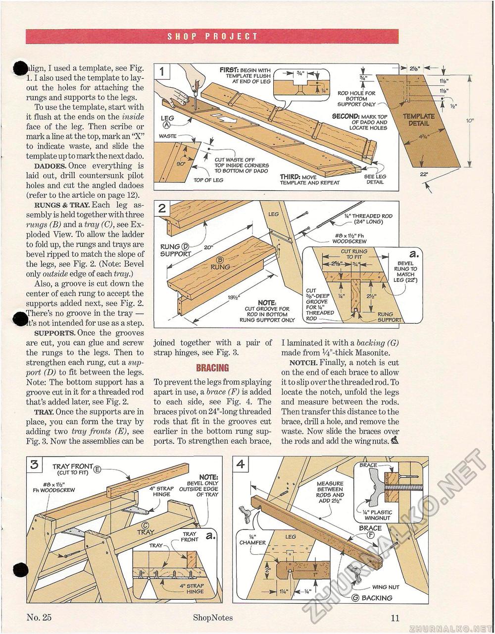
SHOP PROJECT ^j^ilign, I used a template, see Fig. 1.1 also used the template to layout the holes for attaching the rungs and supports to the legs. To use the template, start with it flush at the ends on the inside face of the leg. Then scribe or mark a line at the top, mark an "X" to indicate waste, and slide the template up to mark the next dado. dadoes. Once everything is laid out, drill countersunk pilot holes and cut the angled dadoes (refer to the article on page 12). rungs & tray. Each leg assembly is held together with three rungs (B) and a tray (C), see Exploded View. To allow the ladder to fold up, the rungs and trays are bevel ripped to match the slope of the legs, see Fig. 2. (Note: Bevel only outside edge of each tray.) Also, a groove is cut down the center of each rung to accept the supports added next, see Fig. 2. ^^There's no groove in the tray — ^Pft's not intended for use as a step. supports. Once the grooves are cut, you can glue and screw the rungs to the legs. Then to strengthen each rung, cut a support (D) to fit between the legs. Note: The bottom support has a groove cut in it for a threaded rod that's added later, see Fig. 2. tray. Once the supports are in place, you can form the tray by adding two tray fronts (E), see Fig. 3. Now the assemblies can be 3/4" T ROD hole for bottom support only waste FIRST: begin with template flush at end of leg cut waste off top inside corners to bottom of dado top of leg SECOND: mark top of dado and locate holes THIRD: move template anp repeat detail TEMPLATE DETAIL rung®—^20" support/-^ CUT RUNG TO FIT rung CUT \ %"-DEEP\ GROOVE \ FOR V4" THREADED VROP--- NOTE: CUT GROOVE FOR ROD IN BOTTOM RUNG SUPPORT ONLY RUNG \ SUPPORT a. bevel rung to match leg (22°) joined together with a pah' of strap hinges, see Fig. 3. BRACING To prevent the legs from splaying apart in use, a brace (F) is added to each side, see Fig. 4. The braces pivot on 24"-long threaded rods that fit in the grooves cut earlier in the bottom rung supports. To strengthen each brace, I laminated it with a backing (G) made from V^'-thick Masonite. notch. Finally, a notch is cut on the end of each brace to allow it to slip over the threaded rod. To locate the notch, unfold the legs and measure between the rods. Then transfer this distance to the brace, chill a hole, and remove the waste. Now slide the braces over the rods and add the wing nuts. ' threaded rod (24" long) #£> x IV2" Fh -- WOODSCREW 10" o tray - (CUT TO FIT) #& x 11/z" Fh WOODSCREW 4" STRAP HINGE NOTE: BEVEL ONLY OUTSIDE EDGE OF TRAY No. 25 ShopNotes 11 |


