43 - Build Your Own Dovetail Jig, страница 19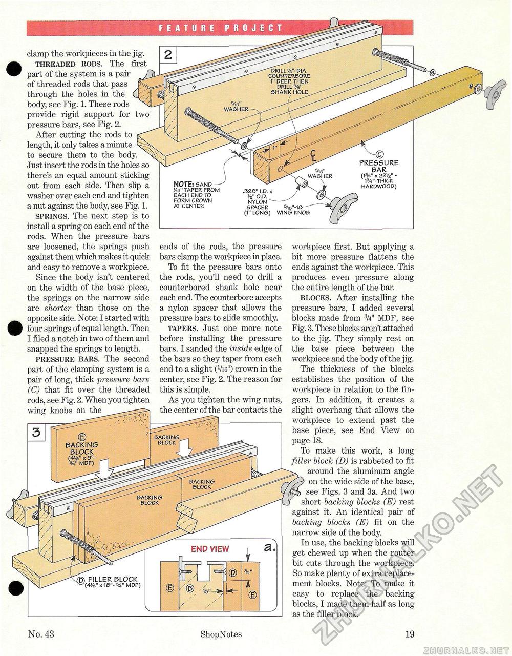
FEATURE PROJECT clamp the workpieces in the jig. threaded rods. The first part of the system is a pair of threaded rods that pass through the holes in the body, see Fig. 1. These rods provide rigid support for two pressure bars, see Fig. 2. After cutting the rods to length, it only takes a minute to secure them to the body. Just insert, the rods in the holes so there's an equal amount sticking out from each side. Then slip a washer over each end and tighten a nut against the body, see Fig. 1. springs. The next step is to install a spring on each end of the rods. When the pressure bars are loosened, the springs push against them which makes it quick and easy to remove a workpiece. Since the body isn't centered on the width of the base piece, the springs on the narrow side are shorter than those on the opposite side. Note: I started with four springs of equal length. Then I filed a notch in two of them and snapped the springs to length. pressure bars. The second part of the clamping system is a pair of long, thick pressure bars (C) that fit over the threaded rods, see Fig. 2. When you tighten wing knobs on the ends of the rods, the pressure bars clamp the workpiece in place. To fit the pressure bars onto the rods, you'll need to drill a counterbored shank hole near each end. The counterbore accepts a nylon spacer that allows the pressure bars to slide smoothly. tapers. Just one more note before installing the pressure bars. I sanded the inside edge of the bars so they taper from each end to a slight (Vie") crown in the center, see Fig. 2. The reason for this is simple. As you tighten the wing nuts, the center of the bar contacts the
workpiece first. But applying a bit more pressure flattens the ends against the workpiece. This produces even pressure along the entire length of the bar. blocks. After installing the pressure bars, I added several blocks made from 3/4" MDF, see Fig. 3. These blocks aren't attached to the jig. They simply rest on the base piece between the workpiece and the body of the jig. The thickness of the blocks establishes the position of the workpiece in relation to the fingers. In addition, it creates a slight overhang that allows the workpiece to extend past the base piece, see End View on page 18. To make this work, a long filler block (D) is rabbeted to fit around the aluminum angle on the wide side of the base, see Figs. 3 and 3a. And two short backing blocks (E) rest against it. An identical pair of backing blocks (E) fit on the narrow side of the body. In use, the backing blocks will get chewed up when the router bit cuts through the workpiece. So make plenty of extra replacement blocks. Note: To make it easy to replace the backing-blocks, I made them half as long as the filler block. No. 43 ShopNotes 19 |


