44 - Grinding Station, страница 19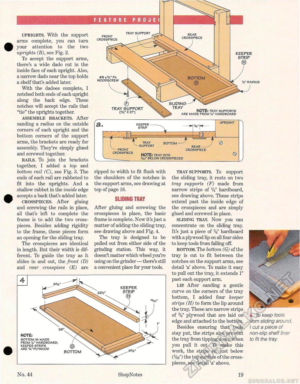
uprights. With the support arms complete, you can turn your attention to the two uprights (B), see Fig. 2. To accept the support arms, there's a wide dado cut in the inside face of each upright. Also, a narrow dado near the top holds a shelf that's added later. With the dadoes complete, I notched both ends of each upright along the back edge. These notches will accept the rails that "tie" the uprights together. assemble brackets. After sanding a radius on the outside corners of each upright and the bottom corners of the support arms, the brackets are ready for assembly. They're simply glued and screwed together. rails. To join the brackets together, I added a top and bottom rail (C), see Fig. 3. The ends of each rail are rabbeted to fit into the uprights. And a shallow rabbet in the inside edge accepts a back that's added later. crosspieces. After gluing and screwing the rails in place, all that's left to complete the frame is to add the two cross-pieces. Besides adding rigidity to the frame, these pieces form an opening for the sliding tray. The crosspieces are identical in length. But their width is different. To guide the tray as it slides in and out, the front (D) and rear crosspiece (E) are a. KEEPER STRIP rr FRONT CROSSPIECE m TRAY SUPPORT BOTTOM rear- ■—'' UPRIGHT 0 REAR-CROSSPIECE NOTE: TRAY SITS Vsz" BELOW CROSSPIECES 0 ripped to width to fit flush with the shoulders of the notches in the support arms, see drawing at top of page 18. SLIDING TRAY After gluing and screwing the crosspieces in place, the basic frame is complete. Now it's just a matter of adding the sliding tray, see drawing above and Fig. 4. The tray is designed to be pulled out from either side of the grinding station. This way, it doesn't matter which wheel you're using on the grinder—there's still a convenient place for your tools. KEEPER STRIP NOTE: BOTTOM IS MADE FROM V4" HARDBOARD; KEEPER STRIPS ARE 3/4" PLYWOOD bottom tray supports. To support the sliding tray, it rests on two tray supports (F) made from narrow strips of V4" hardboard, see drawing above. These strips extend past the inside edge of the crosspieces and are simply glued and screwed in place. sliding tray. Now you can concentrate on the sliding tray. It's just a piece of V4" hardboard with a plywood lip on all four sides ■ to keep tools from falling off. bottom. The bottom (G) of the tray is cut to fit between the notches on the support arms, see detail 'a' above. To make it easy to pull out the tray, it extends 1" past each support arm. lip After sanding a gentle curve on the corners of the tray bottom, I added four keeper strips (H) to form the lip around the tray. These are narrow strips of plywood that are laid on edge and attached to the bottom. Besides ensuring that tools stay put, the strips also prevent the tray from tipping down when you pull it out. To make this work, the strips sit just below (V32") the top surface of the cross-pieces, see detail 'a' above. jtp ■ A To keep tools from sliding around, I cut a piece of non-slip shelf liner to fit the tray. No. 44 ShopNotes 19 TRAY SUPPORT FRONT CROSSPIECE KEEPER STRIP 1/2" RADIUS TRAY NOTE: TRAY SUPPORTS ARE MADE FROM V4" HARDBOARD #S x3A" Fh WOODSCREW TRAY SUPPORT (1 Vz" X 21") REAR CROSSPIECE |


