44 - Grinding Station, страница 22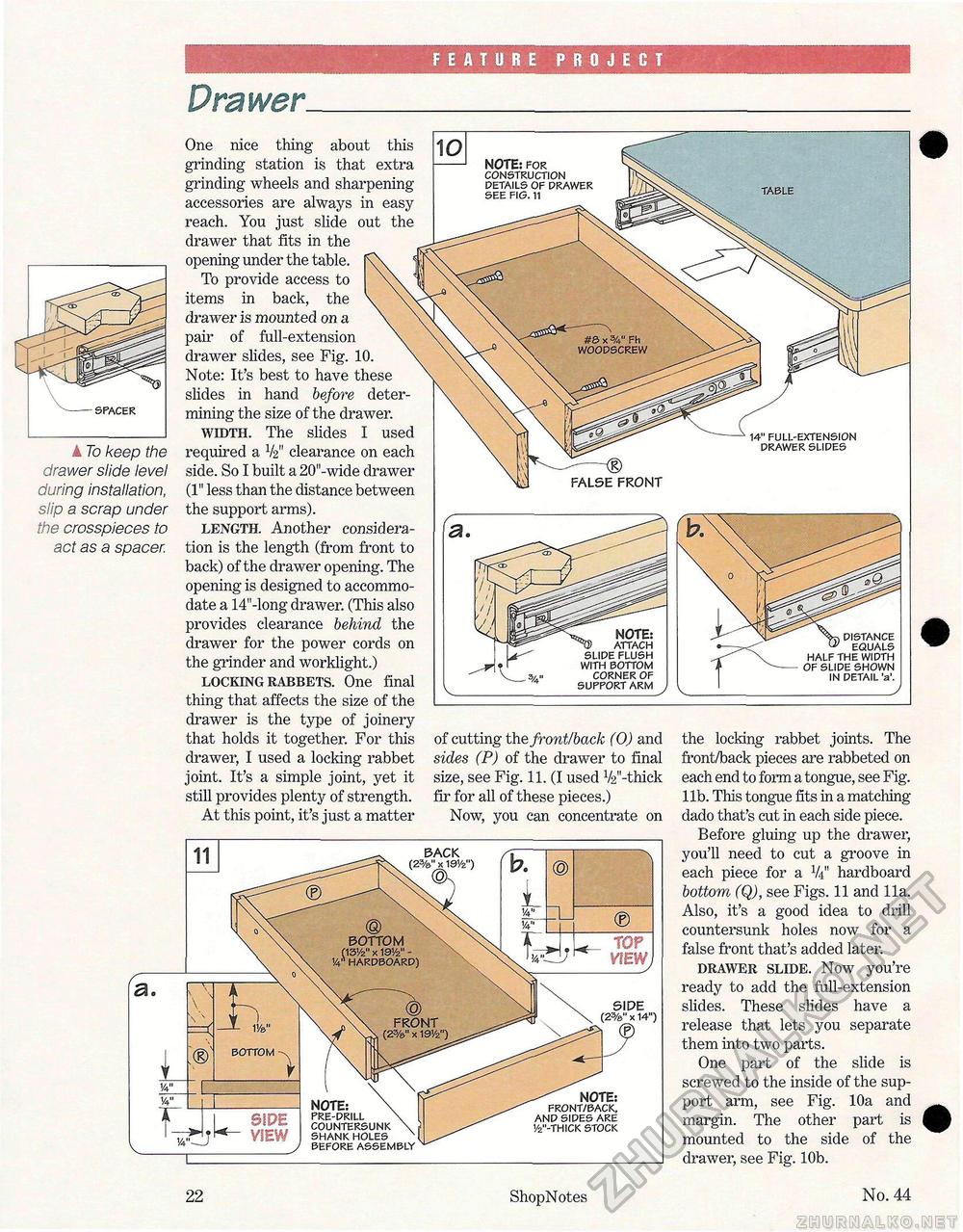
feature project Drawer. ----SPACER A To keep the drawer slide level during installation, slip a scrap under the crosspieces to act as a spacer. of cutting the front/back (0) and sides (P) of the drawer to final size, see Fig. 11. (I used 1/2,,-thiek fir for all of these pieces.) Now, you can concentrate on One nice thing about this grinding station is that extra grinding wheels and sharpening accessories are always in easy reach. You just slide out the drawer that fits in the opening under the table. To provide access to items in back, the drawer is mounted on a pair of full-extension drawer slides, see Fig. 10. Note: It's best to have these slides in hand before determining the size of the drawer. width. The slides I used required a V2" clearance on each side. So I built a 20"-wide drawer (1" less than the distance between the support arms). length. Another consideration is the length (from front to back) of the drawer opening. The opening is designed to accommodate a 14"-long drawer. (This also provides clearance behind the drawer for the power cords on the grinder and worklight.) locking rabbets. One final thing that affects the size of the drawer is the type of joinery that holds it together. For this drawer, I used a locking rabbet joint. It's a simple joint, yet it still provides plenty of strength. At this point, it's just a matter the locking rabbet joints. The front/back pieces are rabbeted on each end to form a tongue, see Fig. lib. This tongue fits in a matching dado that's cut in each side piece. Before gluing up the drawer, you'll need to cut a groove in each piece for a V4" hardboard bottom (Q), see Figs. 11 and 11a. Also, it's a good idea to drill countersunk holes now for a false front that's added later. drawer slide. Now you're ready to add the full-extension slides. These slides have a release that lets you separate them into two parts. One part of the slide is screwed to the inside of the support arm, see Fig. 10a and margin. The other part is mounted to the side of the drawer, see Fig. 10b. NOTE: for CONSTRUCTION DETAILS OF DRAWER FALSE FRONT 14" FULL-EXTENSION DRAWER SLIDES NOTE: ATTACH SLIDE FLUSH WITH BOTTOM CORNER OF SUPPORT ARM TABLE BACK bottom Ci3Vz" x 191/2" -14"' HARDBOARD) FRONT (2%" x 191/2") BOTTOM SIPE VIEW NOTE: PRE-DRILL COUNTERSUNK SHANK HOLES BEFORE ASSEMBLY NOTE: FRONT/BACK, AND SIDES ARE 1/2"-THICK STOCK TOP 22 ShopNotes No. 44 |


