62 - Box Joint Jig, страница 9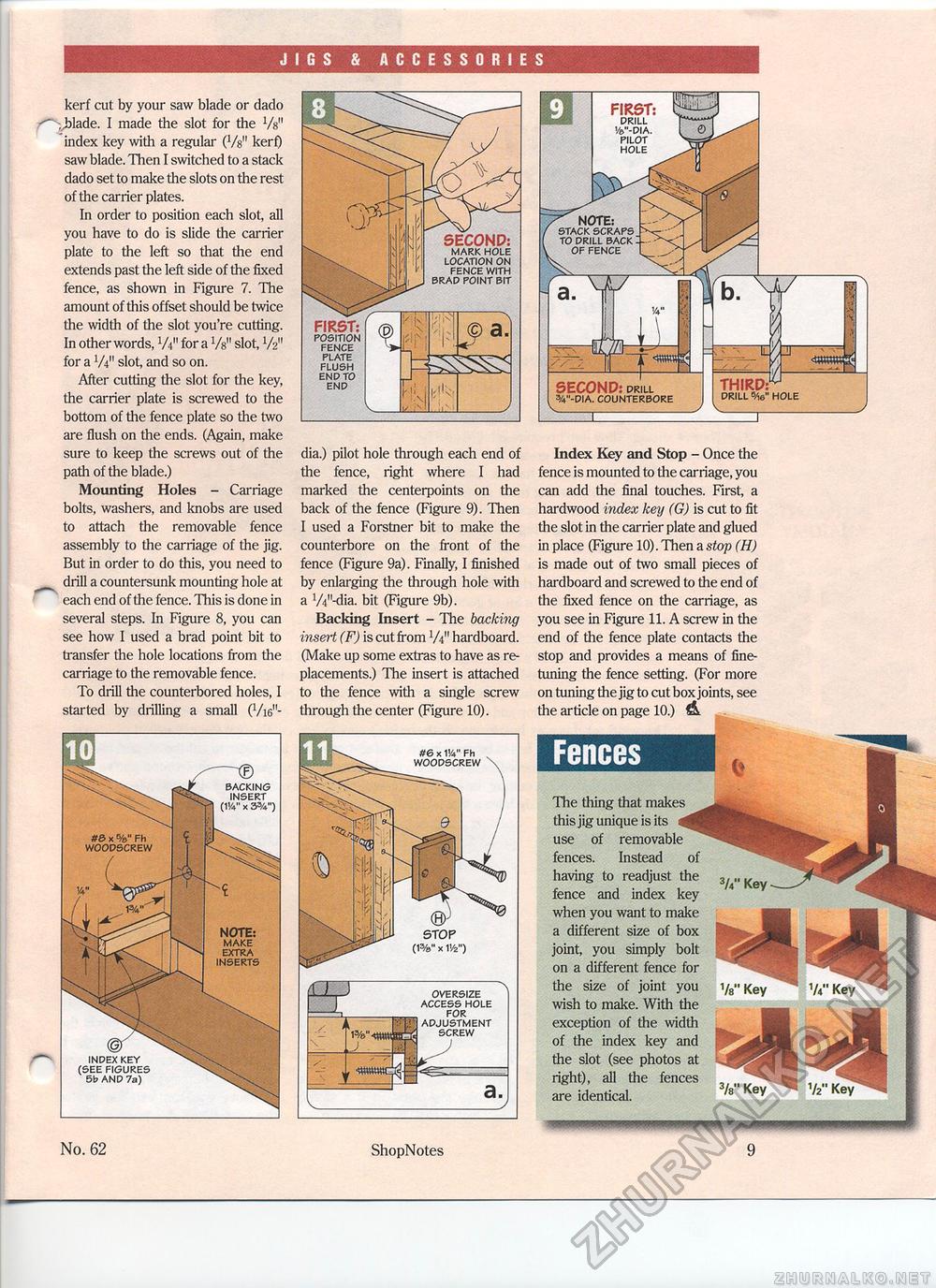
JIGS & ACCESSORIES kerf cut by your saw blade or dado ,_hlade. I made the slot for the Vs" index key with a regular (Vs" kerf) saw blade. Then I switched to a stack dado set to make the slots on the rest of the carrier plates. In order to position each slot, all you have to do is slide the carrier plate to the left so that the end extends past the left side of the fixed fence, as shown in Figure 7. The amount of this offset should be twice the width of the slot you're cutting. In other words, W for a Vs" slot, V2" for a V4'1 slot, and so on. After cutting the slot for the key, the carrier plate is screwed to the bottom of the fence plate so the two are flush on the ends. (Again, make sure to keep the screws out of the path of the blade.) Mounting Holes - Carriage bolts, washers, and knobs are used to attach the removable fence assembly to the carriage of the jig. But in order to do this, you need to drill a countersunk mounting hole at each end of the fence. This is done in several steps. In Figure 8, you can see how I used a brad point bit to transfer the hole locations from the carriage to the removable fence. To drill the counterbored holes, I started by drilling a small (Vi6n- dia.) pilot hole through each end of the fence, right where I had marked the centerpoints on the back of the fence (Figure 9). Then I used a Forstner bit to make the counterbore on the front of the fence (Figure 9a). Finally, I finished by enlarging the through hole with a W'-dia. bit (Figure 9b). Backing Insert - The backing insert (F) is cut from V4" hardboard. (Make up some extras to have as replacements.) The insert is attached to the fence with a single screw through the center (Figure 10). Index Key and Stop - Once the fence is mounted to the carriage, you can add the final touches. First, a hardwood index key (G) is cut to fit the slot in the carrier plate and glued in place (Figure 10). Then a stop (H) is made out of two small pieces of hardboard and screwed to the end of the fixed fence on the carriage, as you see in Figure 11. A screw in the end of the fence plate contacts the stop and provides a means of fine-tuning the fence setting. (For more on tuning the jig to cut box joints, see the article on page 10.) FencesThe tiling that makes this jig unique is its use of removable fences. Instead of having to readjust the fence and index key when you want to make a different size of box joint, you simply bolt on a different fence for the size of joint you wish to make. With the exception of the width of the index key and the slot (see photos at right), all the fences are identical. 3/8" Key FIRST: POSITION FENCE PLATE FLUSH END TO END FIRST: DRILL Vfc"-DIA. PILOT HOLE SECOND: drill %"-dia. counterbore V___ hole BACKING INSERT (114" x 3%") NOTE: make extra inserts INDEX KEY (SEE FIGURES 5b AND 7a) #S x %" Fh woodscrew #6 x 114" Fh WOODSCREW OVERSIZE ACCESS HOLE FOR ADJUSTMENT SCREW No. 62 ShopNotes 9 |


