80 - Heirloom Tool Cabinet, страница 22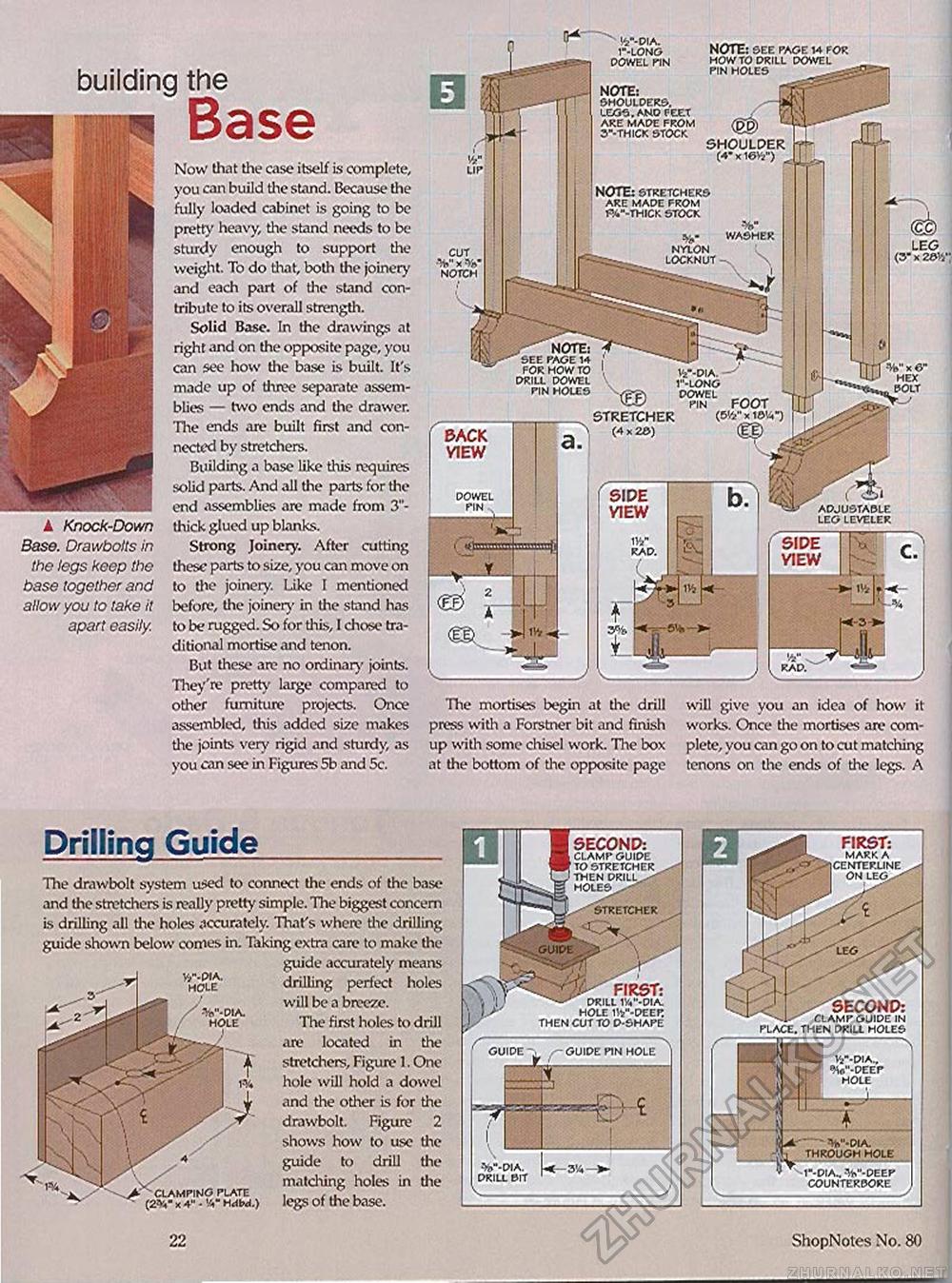
building the A Knock-Down Base. Drawbolts in the legs keep the base together and allow you to take it apart easily. Now that the case itself Is complete, you can build the stand. Because the fully loaded cabinet is going to be pretty heavy, the stand needs to be sturdy enough to support the weight. To do that, both the joinery and each part of the stand contribute to its overall strength. Solid Base. In the drawings at right and on the opposite page, you can see how the base Is built. It's made up of three separate assemblies — two ends and the drawer. The ends are built first and connected by stretchers. Building a base like this requires solid parts. And all the parts for the end assemblies are made from 3"-thick glued up blanks. Strong Joinery. After cutting these parts to size, you can move on to the joiner,'. Like I mentioned before, the joiner)' in the stand has to be rugged. So for this, I chose traditional mortise and tenon. But these arc no ordinary joints. They're pretty large compared to other furniture projects. Once assembled, this added size makes the joints very rigid and sturdy, as you can see in Figures 5b and 5c. The mortises begin at the drill press with a Forstner bit and finish up with some chisel work. The box at the bottom of the opposite page will give you an idea of how it works. Once the mortises are complete, you can go on to cut matching tenons on the ends of the legs. A Drilling Guide 1"-LONG DOWEL riN SHOULDER (4* x1w) NOTE: STRETCHERS ARE MADE FROM PA--THICK STOCK ygT WASHER NYLON LOCKNUT —> CUT x NOTCH ., NOTE: SEE PAGE 14 FOR HOW TO DRILL DOWEL PIN HOLES tV-DIA. -1"-LONG DOWEL „ - PIN FOOT (5'//' x I©'/*") ADJUSTABLE LEG LEVELER NOTE: SHOULDERS. LEGS. AND FEET ARE MADE FROM 3"-THICK STOCK NOTE: SEE PAGE 14 FOR HOW TO DRILL DOWEL PIN HOLES BACK VIEW TVr m SIDE VIEW The drawbolt system u:>ed to connect the ends of the base and the stretchers is really pretty simple. The biggest concern is drilling all tine holes Accurately. Thafs where the drilling guide shown below comes in. Taking extra care to make the guide accurately means drilling perfect holes will be a breeze. The first holes to drill are located in the stretchers, Figure 1. One hole will hold a dowel and the other is for the drawbolt. Figure 2 shows how to use the guide to drill the matching holes in the legs of the base. SECOND: CLAMP GUIDE TO STRETCHER THEN DRILLS HOLES STRETCHER FIRST: ^ DRILL 1V-DIA. HOLE 1V-DEEP. THEN CUT TO D-SHAPE PIN HOLE FIRST: MARK A ICENTERUNE ON LEG^ <' /^SECOND: CLAMP GUIDE IN PLACE. THEN DRILL HOLES ^-•DIA., *V-DEEP HOLE * - W-DIA. THROUGH HOLE 1"-DIA^ -V-DEEP COUNTERBORE 22 ShopNotes No. 80 |


