93, страница 23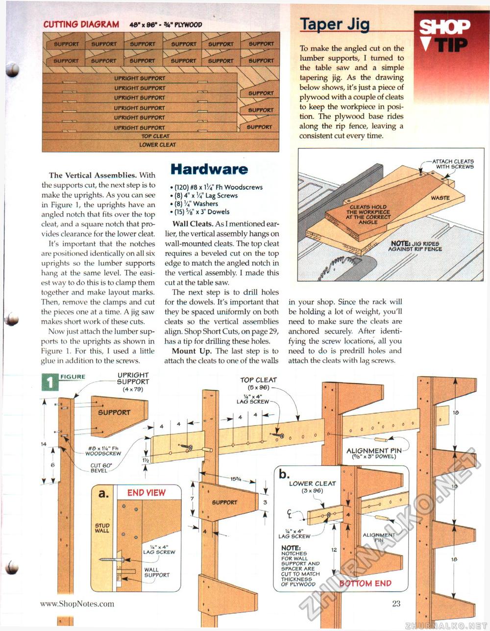
cutting diagram 4&- x 96" - w plywood
The Vertical Assemblies. With the supports cut, the next step is to make the uprights. As you can see in Figure 1, the uprights have an angled notch that fits over the top cleat, and a square notch that provides clearance for the lower cleat. It's important that the notches are positioned identically on all six uprights so the lumber supports hang at the same level. The easiest way to do this is to clamp them together and make layout marks. Then, remove the clamps and cut the pieces one at a time. A jig saw makes short work of these cuts. Now just attach the lumber supports to the uprights as shown in Figure 1. For this, I used a little glue in addition to the screws. Hardware • (120) 08 x V/a Fh Woodscrews • (8) 4" x Lag Screws • (8) V4" Washers • (15) 5/8" x 3" Dowels Wall Cleats. As I mentioned earlier, the vertical assembly hangs on wall-mounted cleats. The top cleat requires a beveled cut on the top edge to match the angled notch in the vertical assembly. I made this cut at the table saw. The next step is to drill holes for the dowels. It's important that they be spaced uniformly on both cleats so the vertical assemblies align. Shop Short Cuts, on page 29, has a tip for drilling these holes. Mount Up. The last step is to attach the cleats to one of the walls Taper Jig To make the angled cut on the lumber supports, I turned to the table saw and a simple tapering jig. As the drawing below shows, it's just a piece of plywood with a couple of cleats to keep the workpiece in position. The plywood base rides along the rip fence, leaving a consistent cut every time. WASTE CLEATS HOLD THE WORKPIECE AT THE CORRECT ANGLE in your shop, Since the rack will be holding a lot of weight, you'll need to make sure the cleats are anchored securely. After identifying the screw locations, all you need to do is predrill holes and attach the cleats with lag screws. note: JIG RIDES AGAINST RIP FENCE -ATTACH CLEATS WITH SCREWS J UPRIGHT SUPPORT (4 x 79) FIGURE TOP CLEAT (5 x 96) — SUPPORT #0 x IV Fh WOODSCREW ALIGNMENT PIN (%" x S" DOWEL) LOWER CLEAT (3 x 96) support STUD WALL V x 4" LAG SCREW ALIGNMENT PIN NOTE: NOTCHES FOR WALL SUPPORT AND SPACER ARE CUT TO MATCH THICKNESS OF PLYWOOD WALL SUPPORT bottom end |
||||||||||||||||||||||||||||||||||||||||||||||||||||||||||||||


