94, страница 39
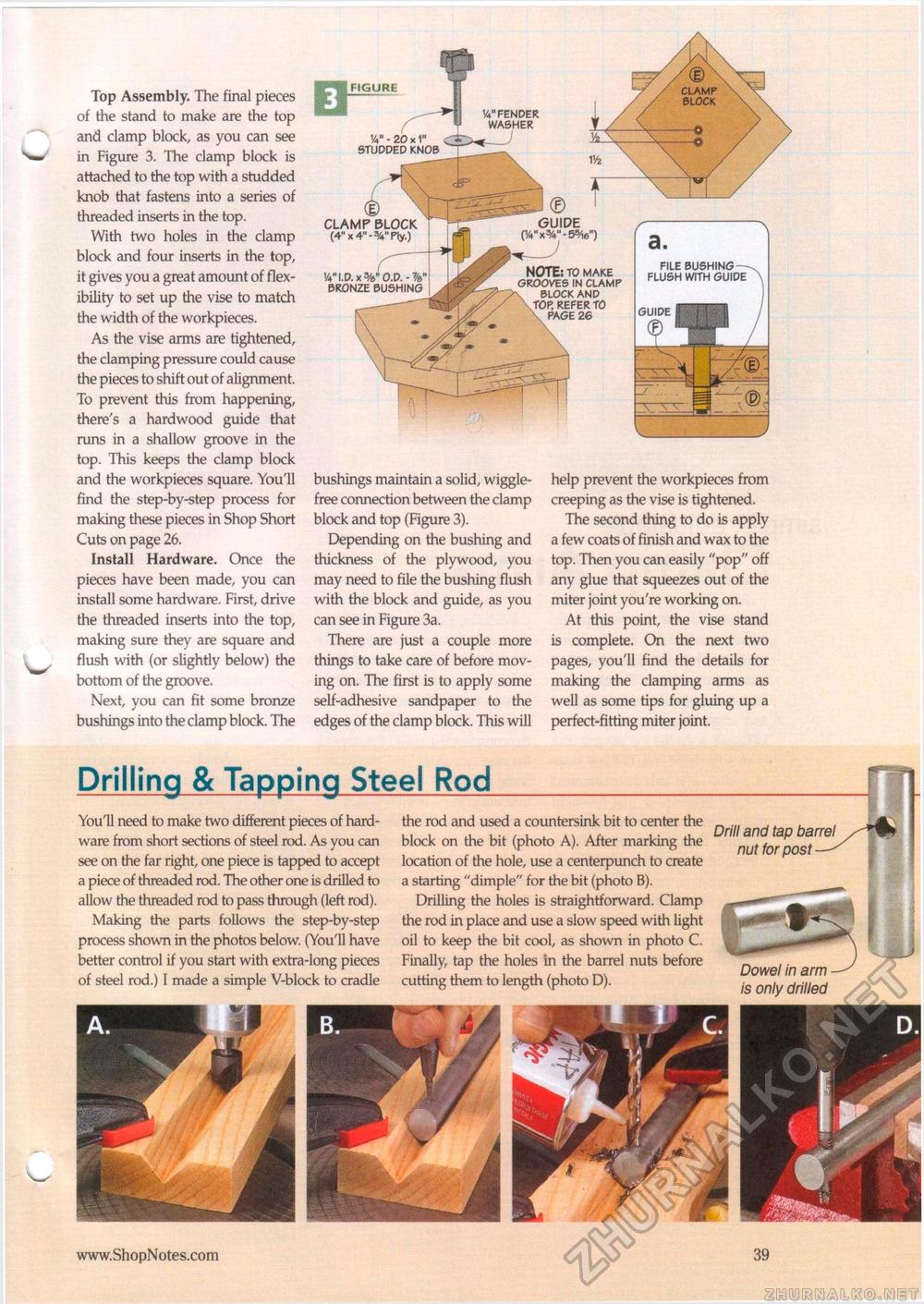
Top Assembly. The final pieces of the stand to make are the top and clamp block, as you can see in Figure 3. The clamp block is attached to the top with a studded knob that fastens into a series of threaded inserts in the top. With two holes in the clamp block and four inserts in the top, it gives you a great amount of flexibility to set up the vise to match the width of the workpieces. As the vise arms are tightened, the clamping pressure could cause the pieces to shift out of alignment. To prevent this from happening, there's a hardwood guide that runs in a shallow groove in the top. This keeps the clamp block and the workpieces square. You'll find the step-by-step process for making these pieces in Shop Short Cuts on page 26. Install Hardware. Once the pieces have been made, you can install some hardware. First, drive the threaded inserts into the top, making sure they are square and flush with (or slightly below) the bottom of the groove. Next, you can fit some bronze bushings into the clamp block. The bushings maintain a solid, wiggle-free connection between the clamp block and top (Figure 3). Depending on the bushing and thickness of the plywood, you may need to file the bushing flush with the block and guide, as you can see in Figure 3a. There are just a couple more things to take care of before moving on. The first is to apply some self-adhesive sandpaper to the edges of the clamp block. This will help prevent the workpieces from creeping as the vise is tightened, The second thing to do is apply a few coats of finish and wax to the top. Then you can easily "pop" off any glue that squeezes out of the miter joint you're working on. At this point, the vise stand is complete. On the next two pages, you'll find the details for making the clamping arms as well as some tips for gluing up a perfect-fitting miter joint. Drilling & Tapping Steel Rod FIGURE Va" - 20 x STUDDED KNOB FILE BUSHING FLUSH WITH GUIDE GUIDE t CLAMP BLOCK (4" x 4" - W Ply.) VI.D.x BRONZE BUSHING Va" FENDER WASHER © ' GUIDE xV-SW) NOTE: TO MAKE GROOVES IN CLAMP BLOCK AND TOP, REFER TO PAGE 26 YouU need to make two different pieces of hardware from short sections of steel rod. As you can see on the far right, one piece is tapped to accept a piece of threaded rod. The other one is drilled to allow the threaded rod to pass through (left rod). Making the parts follows the step-by-step process shown in the photos below. (You'll have better control if you start with extra-long pieces of steel rod.) I made a simple V-block to cradle the rod and used a countersink bit to center the block on the bit (photo A). After marking the location of the hole, use a centerpunch to create a starting "dimple" for the bit (photo B). Drilling the holes is straightforward. Clamp the rod in place and use a slow speed with light oil to keep the bit cool, as shown in photo C. Finally, tap the holes in the barrel nuts before cutting them to length (photo D). Drill and tap barrel nut for post Dowel in arm is only drilled • 39 |


