94, страница 40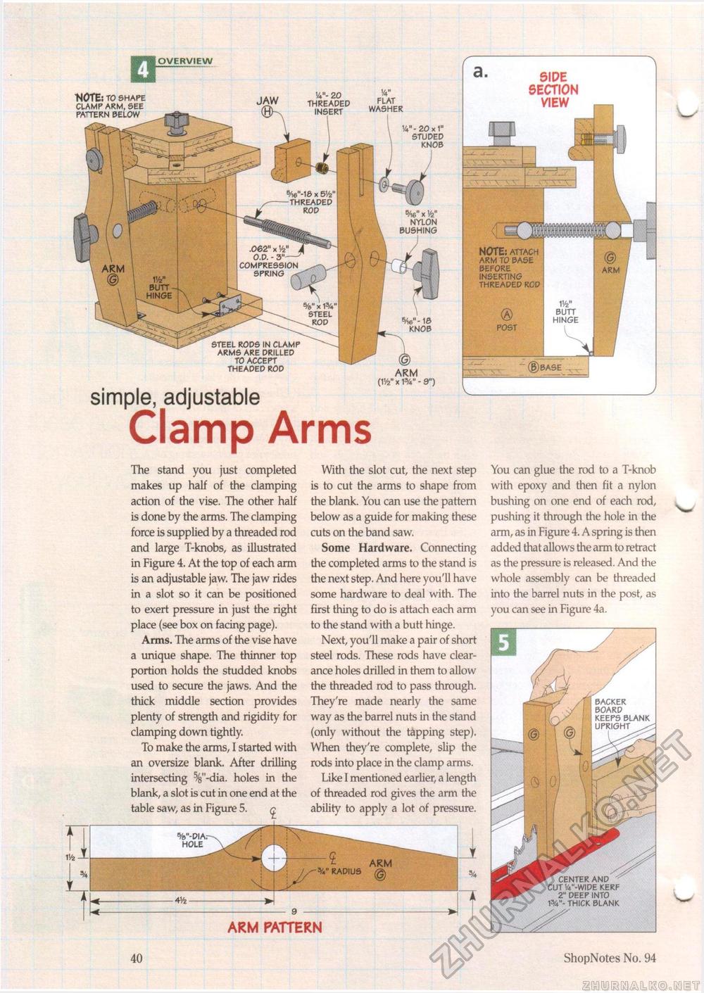
V-1& * 5V2' -threaped rod .062" xW , o.d. - 3"- compression spring ^ V/2" butt -hinge OVERVIEW "NOTE; to shape clamp arm, see pattern below W- 20 1/4" threaded flat insert washer VV- 20 x 1" studed knob 6/16" x Vfe" nylon bushing knob steel rods in clamp arms are drilled to accept theaded rod simple, adjustable Clamp Arms{V/2" ARM X w - 9") The stand you just completed makes up half of the clamping action of the vise. The other half is done by the arms. The clamping force is supplied by a threaded rod and large T-knobs, as illustrated in Figure 4. At the top of each arm is an adjustable jaw. The jaw rides in a slot so it can be positioned to exert pressure in just the right place (see box on facing page). Arms. The arms of the vise have a unique shape. The thinner top portion holds the studded knobs used to secure the jaws. And the thick middle section provides plenty of strength and rigidity for clamping down tightly. To make the arms, I started with an oversize blank. After drilling intersecting %"-dia. holes in the blank, a slot is cut in one end at the table saw, as in Figure 5. <£ With the slot cut, the next step is to cut the arms to shape from the blank. You can use the pattern below as a guide for making these cuts on the band saw. Some Hardware. Connecting the completed arms to the stand is the next step. And here you'll have some hardware to deal with. The first thing to do is attach each arm to the stand with a butt hinge. Next, you'll make a pair of short steel rods. These rods have clearance holes drilled in them to allow the threaded rod to pass through. They're made nearly the same way as the barrel nuts in the stand (only without the tapping step). When they're complete, slip the rods into place in the clamp arms. Like I mentioned earlier, a length of threaded rod gives the arm the ability to apply a lot of pressure. You can glue the rod to a T-knob with epoxy and then fit a nylon bushing on one end of each rod, pushing it through the hole in the arm, as in Figure 4. A spring is then added that allows the arm to retract as the pressure is released. And the whole assembly can be threaded into the barrel nuts in the post, as you can see in Figure 4a. ARM PATTERN 40 ShopNotes No. 94 center and cut 'a"-wide kerf 2" deep into 1%"- thick blank backer board keeps blank |


