50 - Table Saw Workstation, страница 21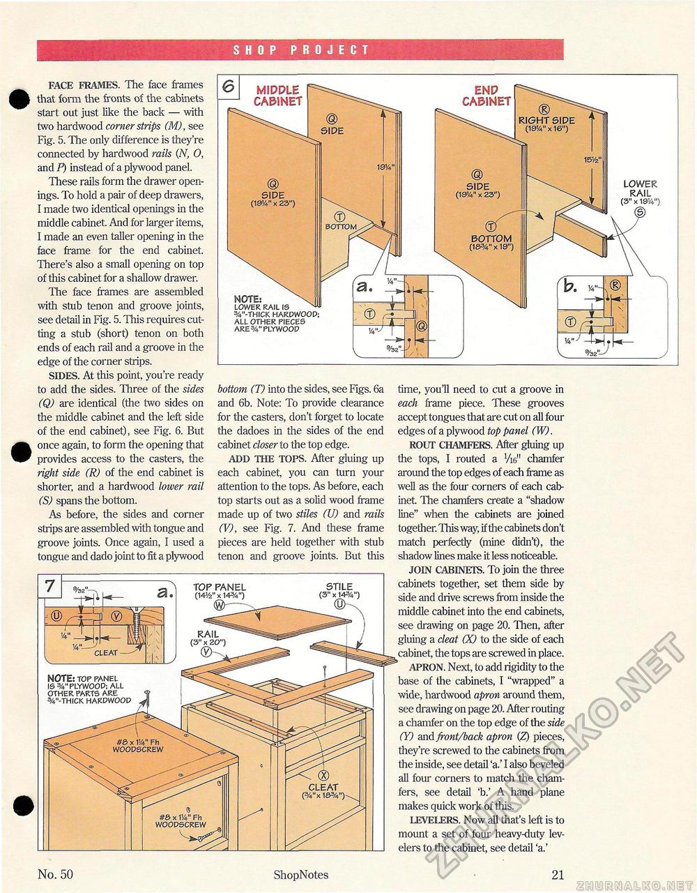
SHOP PROJECT FACE FRAMES. The face frames that form the fronts of the cabinets start out just like the back — with two hardwood corner strips (M), see Fig. 5. The only difference is they're connected by hardwood rails (.N, 0, and P) instead of a plywood panel. These rails form the drawer openings. To hold a pair of deep drawers, I made two identical openings in the middle cabinet. And for larger items, I made an even taller opening in the face frame for the end cabinet. There's also a small opening on top of this cabinet for a shallow drawer. The face frames are assembled with stub tenon and groove joints, see detail in Fig. 5. This requires cutting a stub (short) tenon on both ends of each rail and a groove in the edge of the corner strips. SIDES. At this point, you're ready to add the sides. Three of the sides (Q) are identical (the two sides on the middle cabinet and the left side of the end cabinet), see Fig. 6. But once again, to form the opening that provides access to the casters, the right side (R) of the end cabinet is shorter, and a hardwood lower rail (S) spans the bottom. As before, the sides and corner strips are assembled with tongue and groove joints. Once again, I used a tongue and dado joint to fit a plywood bottom (T) into the sides, see Figs. 6a and 6b. Note: To provide clearance for the casters, don't forget to locate the dadoes in the sides of the end cabinet closer to the top edge. ADD THE TOPS. After gluing up each cabinet, you can turn your attention to the tops. As before, each top starts out as a solid wood frame made up of two stiles (U) and rails (V), see Fig. 7. And these frame pieces are held together with stub tenon and groove joints. But this time, you'll need to cut a groove in each frame piece. These grooves accept tongues that are cut on all four edges of a plywood top panel (W). ROUT CHAMFERS. After gluing up the tops, I routed a V16" chamfer around the top edges of each frame as well as the four corners of each cabinet The chamfers create a "shadow line" when the cabinets are joined together. This way, if the cabinets don't match perfectly (mine didn't), the shadow lines make it less noticeable. JOIN CABINETS. To join the three cabinets together, set them side by side and drive screws from inside the middle cabinet into the end cabinets, see drawing on page 20. Then, after gluing a cleat (X) to the side of each cabinet, the tops are screwed in place. APRON. Next, to add rigidity to the base of the cabinets, I "wrapped" a wide, hardwood apron around them, see drawing on page 20. After routing a chamfer on the top edge of the side (Y) and front/back apron (Z) pieces, they're screwed to the cabinets from the inside, see detail 'a.' I also beveled all four corners to match the chamfers, see detail 'b.' A hand plane makes quick work of this. LEVELERS. Now all that's left is to mount a set of four heavy-duty lev-elers to the cabinet, see detail 'a.' LOWER RAIL (3" x 191A") MIDPLE CA&1NET END CABINET (§) SIDE (19!4" x 23") © SIDE (19V x 23") NOTE: LOWER RAIL IS 3/4"-THICK HARDWOOD; ALL OTHER PIECES ARE PLYWOOD No. 50 ShopNotes 21 |


