50 - Table Saw Workstation, страница 22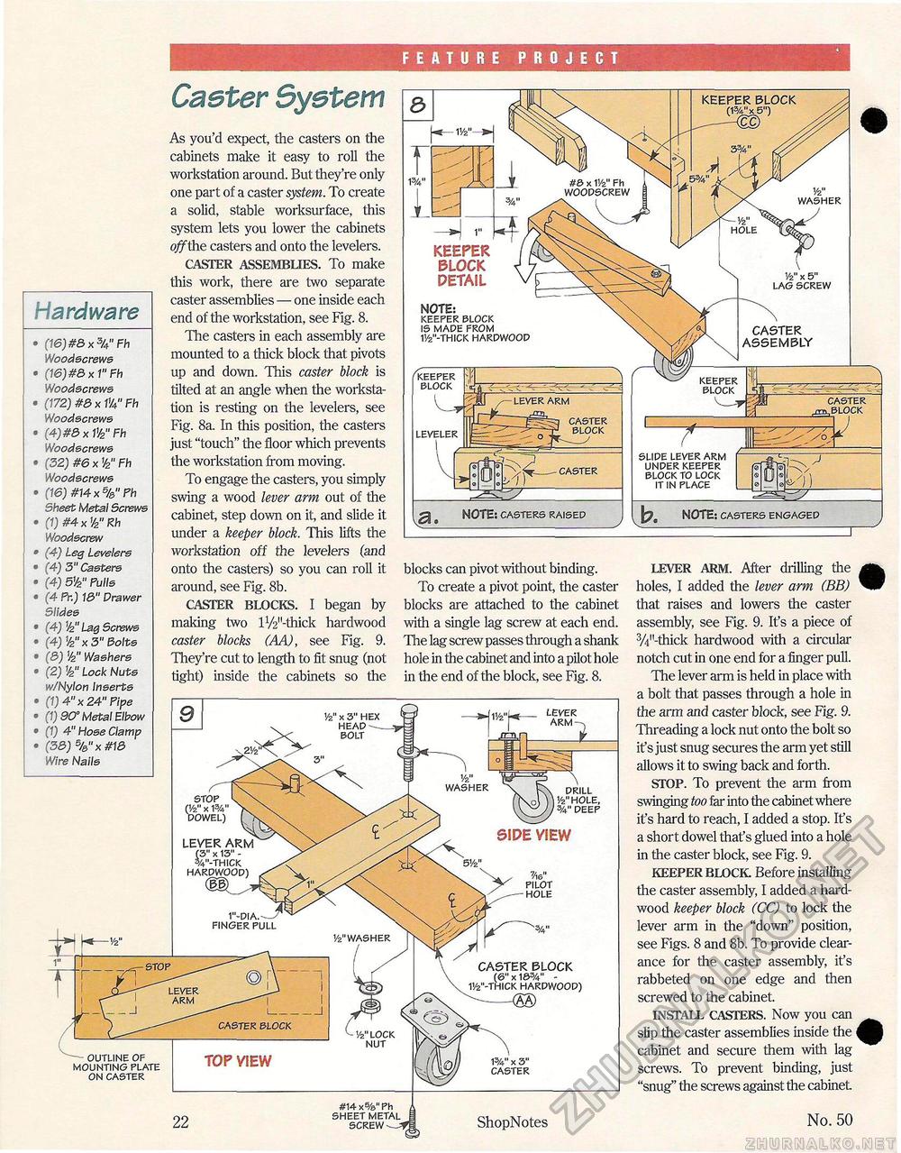
FEATURE PROJECT KEEPER BLOCK As you'd expect, the casters on the cabinets make it easy to roll the workstation around. But they're only one part of a caster system. To create a solid, stable worksurface, this system lets you lower the cabinets off the casters and onto the levelers. CASTER ASSEMBLIES. To make this work, there are two separate caster assemblies — one inside each end of the workstation, see Fig. 8. The casters in each assembly are mounted to a thick block that pivots up and down. This caster block is tilted at an angle when the workstation is resting on the levelers, see Fig. 8a. In this position, the casters just "touch" the floor which prevents the workstation from moving. To engage the casters, you simply swing a wood lever arm out of the cabinet, step down on it, and slide it under a keeper block. This lifts the workstation off the levelers (and onto the casters) so you can roll it around, see Fig. 8b. CASTER BLOCKS. I began by making two lV^'-thick hardwood caster blocks (AA), see Fig. 9. They're cut to length to fit snug (not tight) inside the cabinets so the #& x V/2" Fh woopscrew 1/2" WASHER hole KEEPER BLOCK PETAIL Hardware NOTE; keeper block is made from 11/2"-thick harpwoop CASTER ASSEMBLY (16)#8x3U"Fh Woodscrews (16) #8 x 1" Fh Woodscrews (172) #8 x W4" Fh Woodscrews (4) #8 x V/2" Fh Woodscrews (32) #6 x W Fh Woodscrews (16) #14 x %" Fh Sheet Metal Screws (1) #4 x W Rh Woodscrew (4) Leg levelers (4) 3" Casters (4) dV2" Fulls (4 Fr.) 18" Drawer Slides (4) V2 tag Screws (4) V2"x 3" Bolts (8) '/2" Washers (2) 1/2" Lock Nuts w/Nylon Inserts (1) 4" x 24" Fipe (1) 90° Metal Elbow (1) 4" Hose Clamp (38) %"x #18 Wire Nails keeper block keeper block caster block slipe lever arm unper keeper block to lock it in place NOTE: casters engaged NOTE: casters raised LEVER ARM. After drilling the holes, I added the lever arm (BB) that raises and lowers the caster assembly, see Fig. 9. It's a piece of 3/4M-thick hardwood with a circular notch cut in one end for a finger pull. The lever arm is held in place with a bolt that passes through a hole in the arm and caster block, see Fig. 9. Threading a lock nut onto the bolt so if s just snug secures the arm yet still allows it to swing back and forth. STOP. To prevent the arm from swinging too far into the cabinet where it's hard to reach, I added a stop. It's a short dowel that's glued into a hole in the caster block, see Fig. 9. KEEPER BLOCK Before installing the caster assembly, I added a hardwood keeper block (CC) to lock the lever arm in the "down" position, see Figs. 8 and 8b. To provide clearance for the caster assembly, it's rabbeted on one edge and then screwed to the cabinet. INSTALL CASTERS. Now you can slip the caster assemblies inside the cabinet and secure them with lag screws. To prevent binding, just "snug" the screws against the cabinet blocks can pivot without binding. To create a pivot point, the caster blocks are attached to the cabinet with a single lag screw at each end. The lag screw passes through a shank hole in the cabinet and into a pilot hole in the end of the block, see Fig. 8. Vz" x 3" HEX HEAP --. bolt washer drill '/2"hole, %"deep stop (1/2" x 1%' dowel) LEVER ARM (3" x 13" -v-thick harpwoop) 7Ae" pilot hole 1"-dia.-—/ finger pull Vz" washer CASTER BLOCK (&" x 16%" -11/2"-thick hardwood) ^—m lever arm CASTER BLOCK 1/z"lock nut — outline of mounting plate on caster TOP VIEW #14 x5/a" Ph sheet metal screw ShopNotes |


