51 - Band Saw Upgrade, страница 21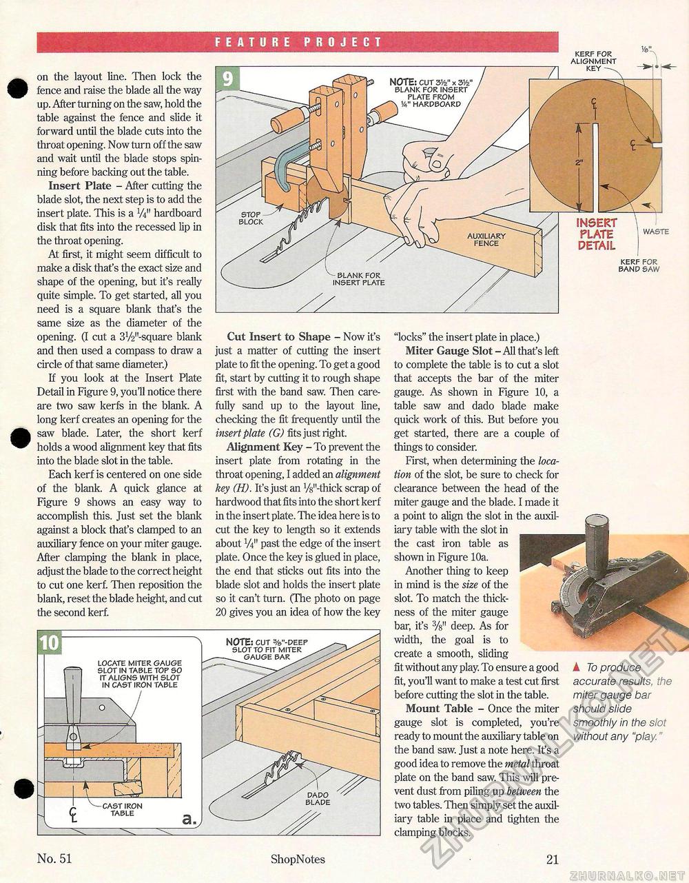
on the layout line. Then lock the fence and raise the blade all the way up. After turning on the saw, hold the table against the fence and slide it forward until the blade cuts into the throat opening. Now turn off the saw and wait until the blade stops spinning before backing out the table. Insert Plate - After cutting the blade slot, the next step is to add the insert plate. This is a W hardboard disk that fits into the recessed lip in the throat opening. At first, it might seem difficult to make a disk that's the exact size and shape of the opening, but it's really quite simple. To get started, all you need is a square blank that's the same size as the diameter of the opening. (I cut a 31/2,,-square blank and then used a compass to draw a circle of that same diameter.) If you look at the Insert Plate Detail in Figure 9, you'll notice there are two saw kerfs in the blank. A long kerf creates an opening for the saw blade. Later, the short kerf holds a wood alignment key that fits into the blade slot in the table. Each kerf is centered on one side of the blank. A quick glance at Figure 9 shows an easy way to accomplish this. Just set the blank against a block that's clamped to an auxiliary fence on your miter gauge. After clamping the blank in place, adjust the blade to the correct height to cut one kerf. Then reposition the blank, reset the blade height, and cut the second kerf. Cut Insert to Shape - Now it's just a matter of cutting the insert plate to fit the opening. To get a good fit, start by cutting it to rough shape first with the band saw. Then carefully sand up to the layout line, checking the fit frequently until the insert plate (G) fits just right. Alignment Key - To prevent the insert plate from rotating in the throat opening, I added an alignment key (H). It's just an V^-thick scrap of hardwood that fits into the short kerf in the insert plate. The idea here is to cut the key to length so it extends about V4" past the edge of the insert plate. Once the key is glued in place, the end that sticks out fits into the blade slot and holds the insert plate so it can't turn. (The photo on page 20 gives you an idea of how the key "locks" the insert plate in place.) Miter Gauge Slot - All that's left to complete the table is to cut a slot that accepts the bar of the miter gauge. As shown in Figure 10, a table saw and dado blade make quick work of this. But before you get started, there are a couple of things to consider. First, when determining the location of the slot, be sure to check for clearance between the head of the miter gauge and the blade. I made it a point to align the slot in the auxiliary table with the slot in the cast iron table as shown in Figure 10a. Another thing to keep in mind is the size of the slot. To match the thickness of the miter gauge bar, it's deep. As for width, the goal is to create a smooth, sliding fit without any play. To ensure a good fit, you'll want to make a test cut first before cutting the slot in the table. Mount Table - Once the miter gauge slot is completed, you're ready to mount the auxiliary table on the band saw. Just a note here. It's a good idea to remove the metal throat plate on the band saw. This will prevent dust from piling up between the two tables. Then simply set the auxiliary table in place and tighten the clamping blocks. A To produce accurate results, the miter gauge bar should slide smoothly in the slot without any "play" NOTE: cur 31/2" x 31/2' blank for insert plate from 14" hardboard / auxiliary fence blank for insert plate FEATURE PROJECT stop block kerf for alignment key INSERT PLATE 1WASTE DETAIL kerf for band saw NOTE: cut %"-deep slot to fit miter locate miter gauge slot in table top so it aligns with slot in cast iron table No. 51 ShopNotes 21 |


