65 - Our Best Bench Yet, страница 20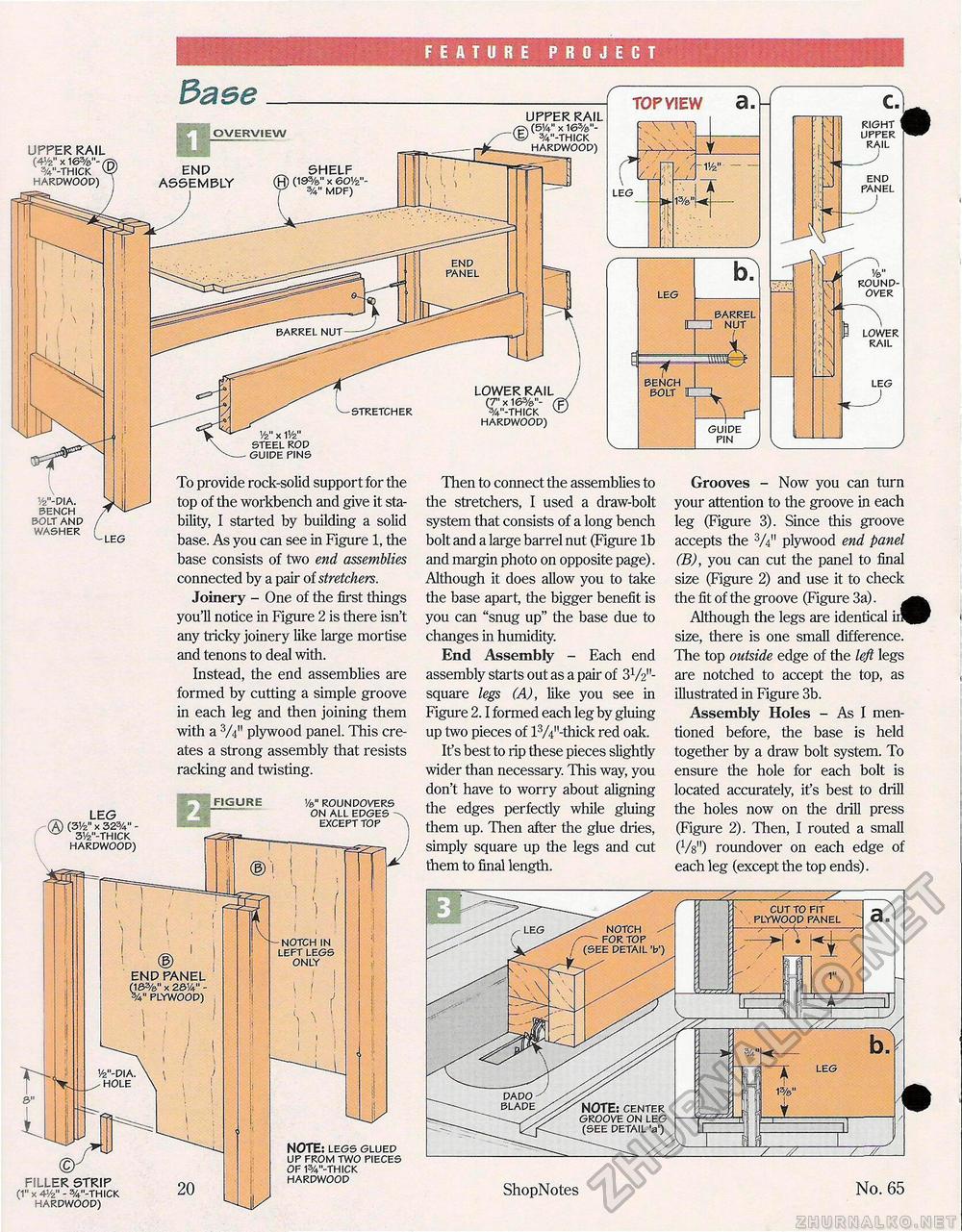
FEATURE PROJECT TOP VIEW a UPPER RAIL \ (514" x 16%"-/ %"-THICK HARDWOOD) RIGHT UPPER RAIL OVERVIEW UPPER RAIL (4</2" x 16%'V W-THICK v HARDWOOD) END PANEL END PANEL 1/e" ROUND-OVER BARREL [r l NUT LOWER RAIL BENCH BOLT LOWER RAIL (7" x 16%"- ( 3/4"-THICK v HARDWOOD) GUIDE PIN y2" x i1/2u STEEL ROD GUIDE PINS To provide rock-solid support for the top of the workbench and give it stability, I started by building a solid base. As you can see in Figure 1, the Then to connect the assemblies to the stretchers, I used a draw-bolt system that consists of a long bench bolt and a large barrel nut (Figure lb Grooves - Now you can turn your attention to the groove in each leg (Figure 3). Since this groove accepts the 3A" plywood end panel v2"-DIA. BENCH BOLT AND WASHER base consists of two end assemblies connected by a pair of stretchers. Joinery - One of the first things you'll notice in Figure 2 is there isn't any tricky joinery like large mortise and tenons to deal with. Instead, the end assemblies are formed by cutting a simple groove in each leg and then joining them with a 3/4m plywood panel. This creates a strong assembly that resists racking and twisting. and margin photo on opposite page). Although it does allow you to take the base apart, the bigger benefit is you can "snug up" the base due to changes in humidity. End Assembly - Each end assembly starts out as a pair of 3V2"-square legs (A), like you see in Figure 2.1 formed each leg by gluing up two pieces of l3/4M-thick red oak. If s best to rip these pieces slightly wider than necessary. This way, you don't have to worry about aligning the edges perfectly while gluing them up. Then after the glue dries, simply square up the legs and cut them to final length. (B), you can cut the panel to final size (Figure 2) and use it to check the fit of the groove (Figure 3a). Although the legs are identical ir^P size, there is one small difference. The top outside edge of the left legs are notched to accept the top, as illustrated in Figure 3b. Assembly Holes - As I mentioned before, the base is held together by a draw bolt system. To ensure the hole for each bolt is located accurately, it's best to drill the holes now on the drill press (Figure 2). Then, I routed a small W) roundover on each edge of each leg (except the top ends). FIGURE Vs." ROUNDOVERS ON ALL EDGES -EXCEPT TOP FILLER STRIP (1" x 4-Vz" - %"-THICK HARDWOOD) NOTCH IN LEFT LEGS ONLY NOTE: LEGS GLUED UP FROM TWO PIECES OF W-THICK HARDWOOD END PANEL (18%" x 2814" -PLYWOOD) |


