65 - Our Best Bench Yet, страница 27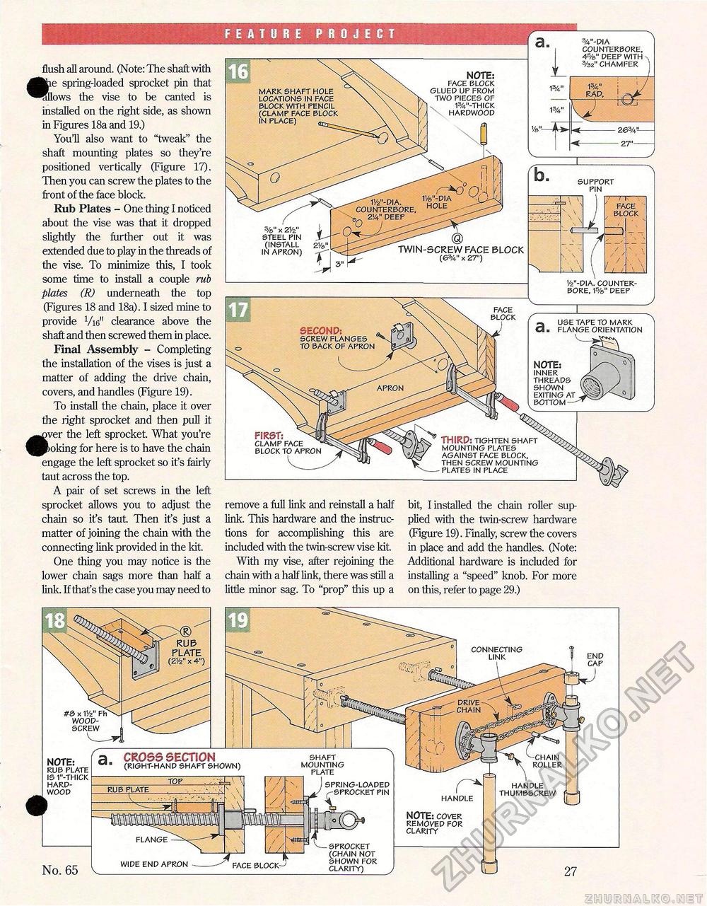
FEATURE PROJECT flush all around. (Note: The shaft with e spring-loaded sprocket pin that ows the vise to be canted is installed on the right side, as shown in Figures 18a and 19.) You'll also want to "tweak" the shaft mounting plates so they're positioned vertically (Figure 17). Then you can screw the plates to the front of the face block. Rub Plates - One thing I noticed about the vise was that it dropped slightly the further out it was extended due to play in the threads of the vise. To minimize this, I took some time to install a couple rub plates (R) underneath the top (Figures 18 and 18a). I sized mine to provide Vi6M clearance above the shaft and then screwed them in place. Final Assembly - Completing the installation of the vises is just a matter of adding the drive chain, covers, and handles (Figure 19). To install the chain, place it over the right sprocket and then pull it •ver the left sprocket. What you're !>oking for here is to have the chain engage the left sprocket so it's fairly taut across the top. A pair of set screws in the left sprocket allows you to adjust the chain so ifs taut. Then it's just a matter of joining the chain with the connecting link provided in the kit. One thing you may notice is the lower chain sags more than half a link. If that's the case you may need to remove a full link and reinstall a half link. This hardware and the instructions for accomplishing this are included with the twin-screw vise kit. With my vise, after rejoining the chain with a half link, there was still a little minor sag. To "prop" this up a bit, I installed the chain roller supplied with the twin-screw hardware (Figure 19). Finally, screw the covers in place and add the handles. (Note: Additional hardware is included for installing a "speed" knob. For more on this, refer to page 29.) %"-dia counterbore, 4deep with %2" chamfer NOTE: face block glued up from two pieces of x 13/4"-thick hardwood mark shaft hole locations in face block with pencil (clamp face block in place) ©a-^. support pin V/e"-QlA hole -TT.—" face block 11/2"-dia. counterbore, 3 2w deep %" x ZVz" i steel pin l- (install 2Ve>' in apron) ' TWIN-SCREW FACE SLOCK (63/V' X 2T) 1/2"-dia. counterbore, 1s/®"deep face block use tape to mark flange orientation SECOND: screw flanges to back of apron NOTE: inner threads shown exiting at bottom —' apron FIRST; clamp face ^ block to apron THIRD: tighten shaft mounting plates against face block, then screw mounting plates in place RUS PLATE end cap #& x V/z" Fh wood-screw NOTE: rub plate is 1"-thick hardwood No. 65 roller 3 CROSS SECTION ■ (right-hand shaft shown) sprocket (chain not shown for clarity) handle NOTE: cover removed for clarity handle thumbscrew spring-loaded pin flange wide end apron v___ shaft mounting plate |


