88, страница 25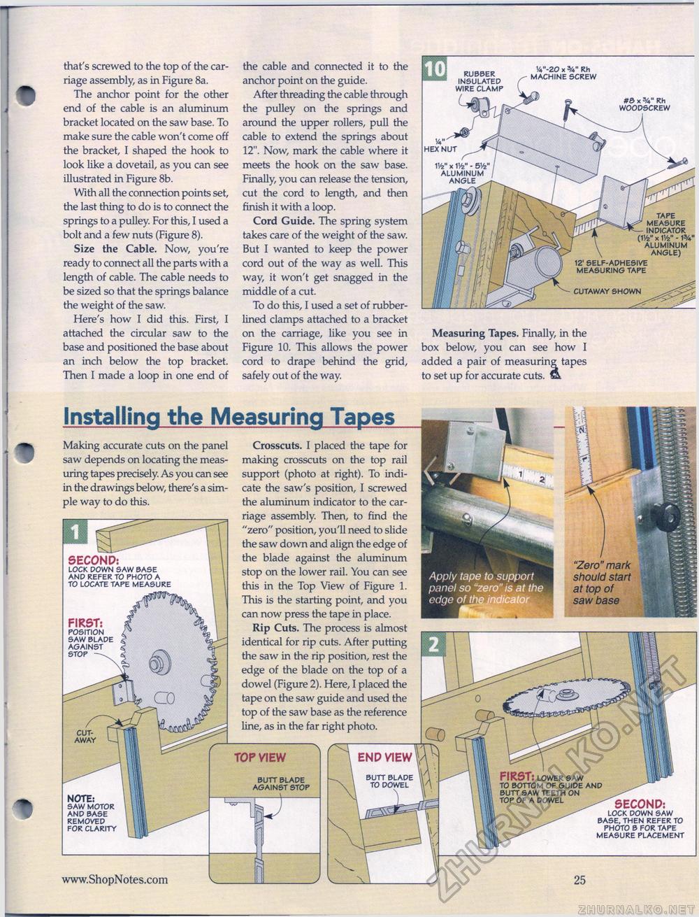
that's screwed to the top of the carriage assembly, as in Figure 8a. The anchor point for the other end of the cable is an aluminum bracket located on the saw base. To make sure the cable won't come off the bracket, I shaped the hook to look like a dovetail, as you can see illustrated in Figure 8b. With all the connection points set, the last thing to do is to connect the springs to a pulley. For this, I used a bolt and a few nuts (Figure 8). Size the Cable. Now, you're ready to connect all the parts with a length of cable. The cable needs to be sized so that the springs balance the weight of the saw. Here's how I did this. First, I attached the circular saw to the base and positioned the base about an inch below the top bracket. Then I made a loop in one end of the cable and connected it to the anchor point on the guide. After threading the cable through the pulley on the springs and around the upper rollers, pull the cable to extend the springs about 12". Now, mark the cable where it meets the hook on the saw base. Finally, you can release the tension, cut the cord to length, and then finish it with a loop. Cord Guide. The spring system takes care of the weight of the saw. But I wanted to keep the power cord out of the way as well. This way, it won't get snagged in the middle of a cut. To do this, I used a set of rubber-lined clamps attached to a bracket on the carriage, like you see in Figure 10. This allows the power cord to drape behind the grid, safely out of the way. Measuring Tapes. Finally, in the box below, you can see how I added a pair of measuring tapes to set up for accurate cuts. & Installing the Measuring TapesMaking accurate cuts on the panel saw depends on locating the measuring tapes precisely. As you can see in the drawings below, there's a simple way to do this. SECOND: LOCK DOWN SAW BASE AND REFER TO PHOTO A TO LOCATE TAPE MEASURE Crosscuts. I placed the tape for making crosscuts on the top rail support (photo at right). To indicate the saw's position, I screwed the aluminum indicator to the carriage assembly. Then, to find the "zero" position, you'll need to slide the saw down and align the edge of the blade against the aluminum stop on the lower rail. You can see this in the Top View of Figure 1. This is the starting point, and you can now press the tape in place. Rip Cuts. The process is almost identical for rip cuts. After putting the saw in the rip position, rest the edge of the blade on the top of a dowel (Figure 2). Here, I placed the tape on the saw guide and used the top of the saw base as the reference line, as in the far right photo. w hex nut V/z" x V/z ■ 5/z ALUMINUM ANGLE tape measure indicator (V/z" x V/z" - W aluminum angle) 12' self-adhesive measuring tape RUBBER INSULATED WIRE CLAMP 'V-20 x 3/4" RH MACHINE SCREW #£> x 3/4" Rh WOODSCREW |


