Woodworker's Journal 1994-18-2, страница 29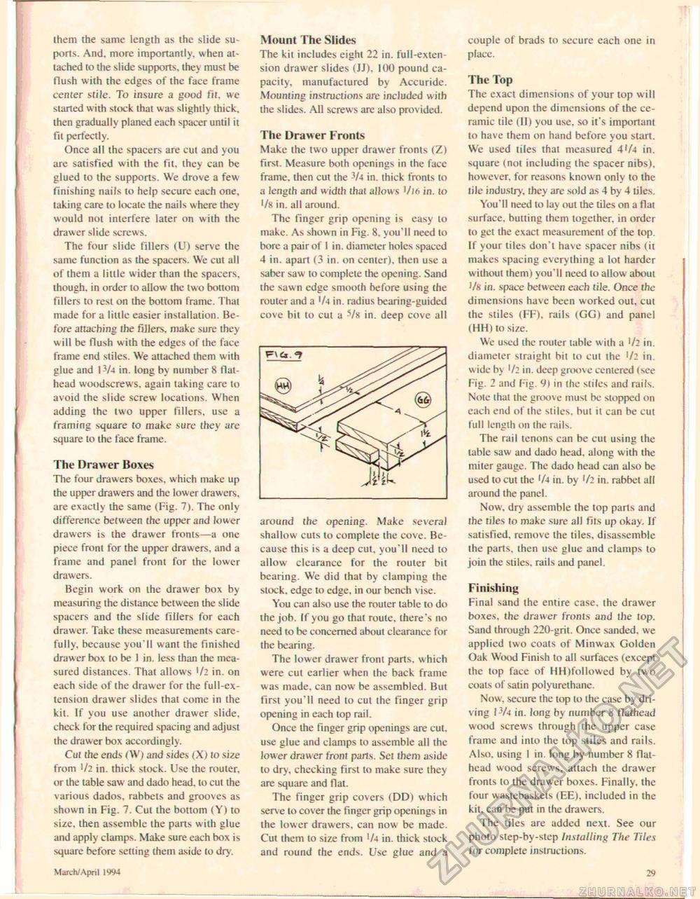
them the same length as the slide su-ports. And. more importantly, when attached to the slide supports, they must be flush with the edges of the face frame center stile. To insure a good fit. we started with stock that was slighUy thick, then gradually planed each spacer until it fit perfectly. Once all the spacers are cut and you are satisfied with the fit, they can be glued to the supports. We drove a few finishing nails to help secure each one, taking care to locate the nails where they would not interfere later on with the drawer slide screws. The four slide fillers (U) serve the same function as the spacers. We cut all of them a little wider than the spacers, though, in order lo allow the two bottom fillers to resi on the bottom frame. That made for a little easier installation. Before attaching the fillers, make sure they will be flush with the edges of the face frame end stiles. We attached them with glue and 13/4 in. long by number 8 flat-head woodscrews. again taking care to avoid the slide screw locations. When adding the two upper fillers, use a framing square to make sure they are square to the face frame. The Drawer Boxes The four drawers boxes, which make up the upper drawers and the lower drawers, are exactly ihe same (Fig. 7). The only difference between the upper and lower drawers is the drawer fronts—a one piece front for the upper drawers, and a frame and panel front for the lower drawers. Begin work on the drawer box by measuring the distance between the slide spacers and the slide fillers for each drawer. Take these measurements carefully. because you'll want the finished drawer box lo be I in. less than the measured distances. That allows Ui in. on each side of the drawer for the full-extension drawer slides that come in the kit. If you use another drawer slide, check for the required spacing and adjust the drawer box accordingly. Cut the ends (W) and sides (X) to size from 1/2 in. thick stock. Use the router, or the table saw and dado head, to cut the various dados, rabbets and grooves as shown in Fig. 7. Cut the bottom (Y) to size, then assemble ihe parts with glue and apply clamps. Make sure each box is square before setting them aside to dry. Mount The Slides The kil includes eight 22 in. full-extension drawer slides (JJ). 100 pound capacity, manufactured by Accuride. Mounting instructions are included with the slides. All screws arc also prov ided. The Drawer Fronts Make the iwo upper drawer fronts (Z) first. Measure both openings in the face frame, then cut the 3/4 in. thick fronts to a length and width that allows Vl6 in. lo ■/8 in. all around. The finger grip opening is easy to make. As shown in Fig. 8, you'll need lo bore a pair of I in. diameter holes spaced 4 in. apart (3 in. on center), then use a saber saw to complete the opening. Sand the sawn edge smooth before using the router and a 'At in. radius bearing-guided cove bil to cut a 5/x in. deep cove all around the opening. Make several shallow cuts lo complete the cove. Because this is a deep cut, you'll need to allow clearance for the router bit bearing. We did that by clamping the slock, edge to edge, in our bench vise. You can also use the router table to do ihe job. If you go that route, there's no need to be concerned about clearance for the bearing. The lower drawer front parts, which were cut earlier when ihe back frame was made, can now be assembled. But first you'll need lo cut ihe finger grip opening in each top rail. Once the finger grip openings are cut. use glue and clamps to assemble all the lower drawer front parts. Set Iheni aside to dry. checking first to make sure they are square and fiat. The finger grip covers (DD) which serve to cover the finger grip openings in the lower drawers, can now be made. Cut them lo size from '/4 in. thick slock and round the ends. Use glue and a couple of brads to secure each one in placc. The Top The exact dimensions of your top will depend upon the dimensions of the ceramic tile (II) you use. so it's important to have them on hand before you start, Wc used tiles that measured 4'/4 in. square (not including the spacer nibs), however, for reasons known only to the tile industry, they are sold as 4 by 4 tiles. You'll need to lay out the tiles on a flat surface, butting them together, in order to get the exact measurement of the top. If your tiles don't have spacer nibs (it makes spacing everything a lot harder without them) you'll need to allow about Vk in. space between each tile. Once the dimensions have been worked out, cut the stiles (FF), rails (GG) and panel (HH) to size. We used the router table with a !/2 in. diameter straight bit to cut ihe I/: in. wide by '/2 in. deep groove centered (see Fig. 2 and Fig. V) in ihe stiles and rails. Note that the groove must be stopped on each end of the stiles, but it can be cut full length on the rails. The rail tenons can be cut using the table saw and dado head, along w ith the miter gauge. The dado head can also be used to cut the '/-»in. by '/2 in. rabbet all around the panel. Now. dry assemble the top parts and ihe tiles to make sure all fils up okay. If satisfied, remove the tiles, disassemble Ihe parts, then use glue and clamps to join the stiles, rails and panel. Finishing Final sand ihe entire case, ihe drawer boxes, the drawer fronts and the top. Sand through 220-grit. Once sanded, we applied two coats of Minwax Golden Oak WikxI Finish lo all surfaces (except the top face of HH (followed by two coats of satin polyurelhane. Now, secure the top to the case by driving P/4 in. long by number S flathead wood screws through the upper case frame and into the top stiles and rails. Also, using 1 in. long by number 8 flat-head wood screws, attach the drawer fronts to the drawer boxes. Finally, the four wastebaskets (EE), included in the kit. can be put in the drawers. The tiles are added next. See our photo sfep-by-step Installing The Tiles for complete instructions. March/ April 1994 29 |


