Woodworker's Journal 2010-34-2, страница 34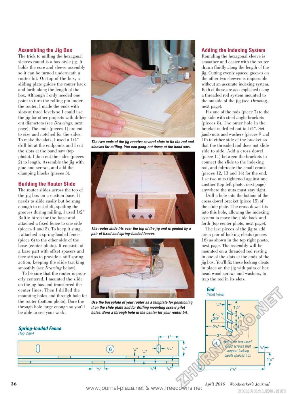
Assembling the Jig Box The trick to milling the hexagonal sleeves round is a box-style jig. It holds the core and sleeve assembly so it can be turned underneath a router bit. On top of the box, a sliding plate guides the router back and forth along the length of the box. Although 1 only needed one point to turn the rolling pin under the router, 1 made the ends with slots at three levels so 1 could use the jig for other projects with different diameters (see Drawings, next page). The ends (pieces 1) are cut to size and notched for the sides. To make the slots, 1 used a 1/4" drill bit at the endpoints and I cut the slots at the band saw (top photo). I then cut the sides (pieces 2) to length. Assemble the jig with glue and screws, and add the clamping blocks (pieces 3). Building the Router Slide The router slides across the top of the jig box on a custom base. It needs to slide easily but be snug enough to not shift, spoiling the grooves during milling. 1 used 1/2" Baltic birch for the base and attached a fixed fence to one side (pieces 4 and 5). To keep it snug, I attached a spring-loaded fence (piece 6) to the other side of the base (center photo). It consists of a base part with offset spacers and face strips to provide a stiff spring action, keeping the slide tracking smoothly (see Drawing below). To be sure that the router is properly centered, I mounted the slide on the jig Ikjx and transferred the center lines. Then 1 drilled the mounting holes and through hole for the router (bottom photo). Bore the through hole large enough so you'll be able to see your work. The two ends of the jig receive several slots to fix the rod and sleeves for milling. You can gang-cut these at the band saw. The router slide fits over the top of the jig and is guided by a pair of fixed and spring-loaded fences. Use the baseplate of your router as a template for positioning it on the slide plate and for drilling mounting screw pilot holes. Bore a through hole in the center for your router bit. Spring-loaded Fence (fop View) 0 ® V rr r -ty 3/,e" * 3/«" •J 3/," L- Adding the Indexing System Rounding the hexagonal sleeve is smoother and easier with the router drawn fluidlv along the length of the jig. Cutting evenly spaced grooves on the other two sleeves is impossible without an accurate indexing system. Both of these are accomplished using a threaded rod system mounted lo the outside of the jig (see Drawing, next page). Fix one of the rods (piece 7) to the jig side with steel angle brackets (pieces 8). The outer hole in the bracket is drilled out to 1/4". Set jamb nuts and washers (pieces 9 and 10) to either side of the bracket so that the threaded rod does not slide side to side. Add a cross dowel (piece 11) between the brackets to connect the slide to the indexing rod, and fabricate the small crank (pieces 12, 13 and 14) for the end. Use two nuts tightened against one another (top left photo, next page) anywhere the nuts must stay tight. Drill a hole into the Ixittom of the cross dowel bracket (piece 15) of the slide plate. The cross dowel fits into this hole, allowing the indexing system to move the slide back and forth (top center photo, next page). The last pieces of the jig to add are a pair of locking cleats (pieces 16) as shown in the top right photo, next page. The assembly will be mounted on a threaded rod resting in one of the slots at the ends of the jig box. You'll fix these locking cleats in place on the jig with pairs of hex head wood screws and washers, lo Irap the rod in its slots. End (Front View) 36 April 2010 Woodworkers Jourruil |


